Toyota Venza: Components
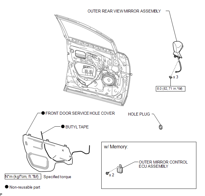
COMPONENTS
ILLUSTRATION
.png)
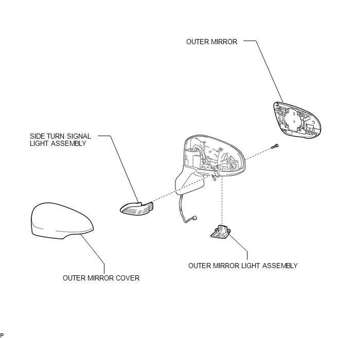
ILLUSTRATION
ILLUSTRATION

 Removal
REMOVAL
PROCEDURE
1. PRECAUTION
NOTICE:
After turning the ignition switch off, waiting time may be required before disconnecting
the cable from the negative (-) battery terminal. Therefore, make ...
Other materials about Toyota Venza:
Installation
INSTALLATION
PROCEDURE
1. INSTALL RADIATOR ASSEMBLY
(a) Install the fan assembly with motor to the radiator with the 2 guides
at the bottom and 3 snap fits on the top.
Text in Illustration
*1
Snap fit
...
Towing related terms
- GCWR (Gross Combination Weight Rating)
► 2GR-FE engine (Without towing package)
and 1AR-FE engine
The maximum allowable gross combination weight. The gross combination weight
is the sum of the total vehicle weight (including the occupants ...
Adjustment
ADJUSTMENT
PROCEDURE
1. ADJUST PARK/NEUTRAL POSITION SWITCH ASSEMBLY
(a) Remove the transmission control shaft lever.
HINT:
See the steps from "Remove Cool Air Intake Duct Seal" through "Remove Park/Neutral
Position Switch Assembly" ...

0.1158