Toyota Venza: Components
COMPONENTS
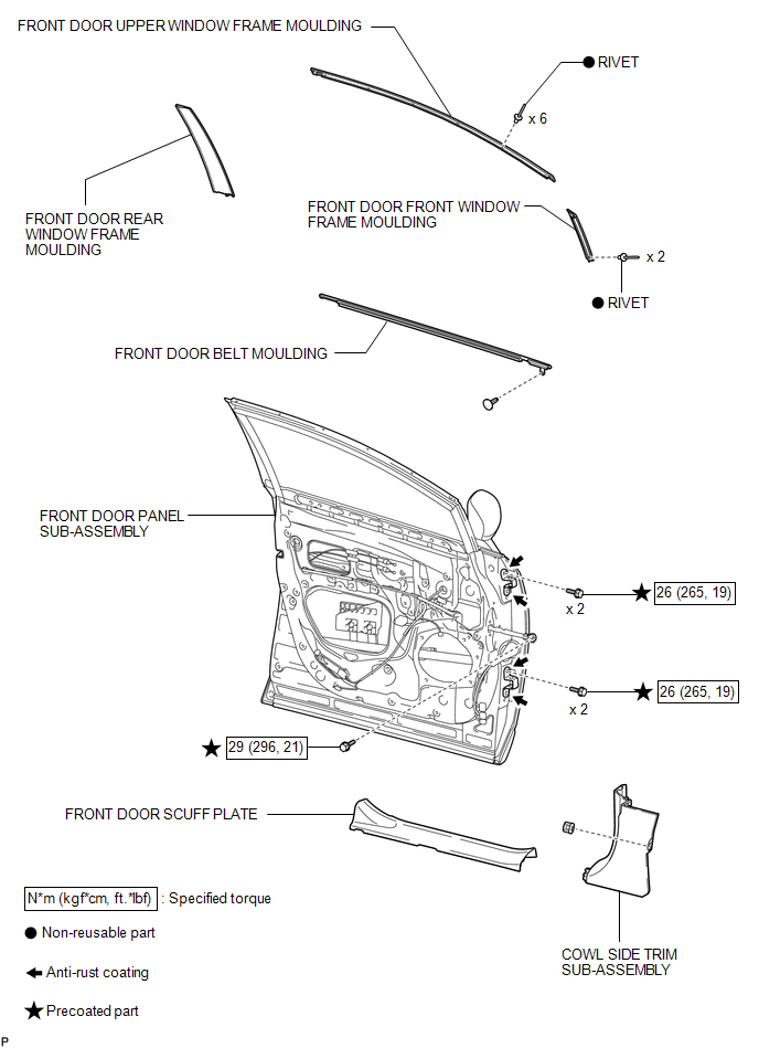
ILLUSTRATION
.png)
ILLUSTRATION
.png)
ILLUSTRATION

 Installation
INSTALLATION
PROCEDURE
1. INSTALL FRONT DOOR FRONT WINDOW FRAME MOULDING
(a) Engage the front door front window frame moulding to the door frame.
...
Other materials about Toyota Venza:
Driving the vehicle
The following procedures should be observed to ensure safe driving.
- Starting the engine
- Driving
With the brake pedal depressed,
shift the shift lever to “D”.
Release the parking brake.
Gradually release the brake pedal
and gentl ...
Definition Of Terms
DEFINITION OF TERMS
Term
Definition
Monitor Description
Description of what the ECM monitors and how it detects malfunctions
(monitoring purpose and details).
Related DTCs
Group ...
Removal
REMOVAL
PROCEDURE
1. PRECAUTION
CAUTION:
Be sure to read Precaution thoroughly before servicing (See page
).
NOTICE:
After turning the ignition switch off, waiting time may be required before disconnecting
the cable from the negative (-) battery term ...

0.154