Toyota Venza: Components
COMPONENTS
ILLUSTRATION
ILLUSTRATION
.png)
ILLUSTRATION
ILLUSTRATION
ILLUSTRATION


 Removal
REMOVAL
PROCEDURE
1. REMOVE REAR WHEELS
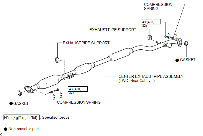
2. REMOVE CENTER EXHAUST PIPE ASSEMBLY
(a) Remove the center exhaust pipe assembly.
HINT:
Refer to the instructions for Removal of the exhaust pipe (See p ...
Other materials about Toyota Venza:
Main Body ECU Communication Stop Mode
DESCRIPTION
Detection Item
Symptom
Trouble Area
Main Body ECU Communication Stop Mode
"Main Body" is not displayed on "CAN Bus Check" screen of the
Techstream.
...
Calculation formula for your vehicle
1. Cargo capacity
2. Total load capacity (vehicle capacity weight)
When 2 people with the combined weight of A lb. (kg) are riding in your vehicle,
which has a total load capacity (vehicle capacity weight) of B lb. (kg), the available
amount of cargo a ...
Short in Torque Converter Clutch Solenoid Circuit (Shift Solenoid Valve SL)
(P2769,P2770)
DESCRIPTION
Shift solenoid valve SL is turned on and off by signals from the TCM to control
the hydraulic pressure acting on the lock-up relay valve, which then controls operation
of the lock-up clutch.
DTC No.
DTC Detection Conditi ...

0.1761