Toyota Venza: Components
COMPONENTS
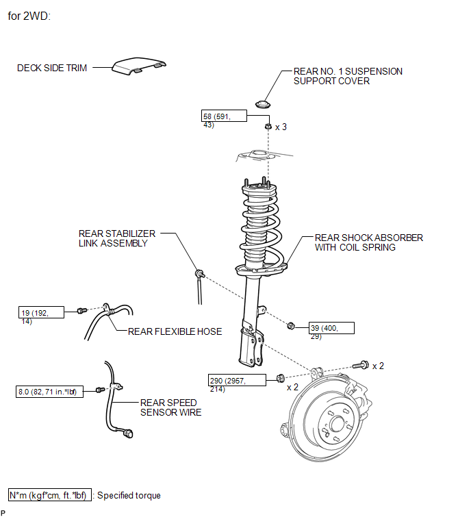
ILLUSTRATION
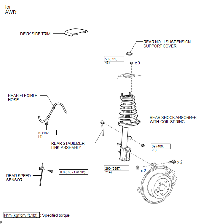
ILLUSTRATION
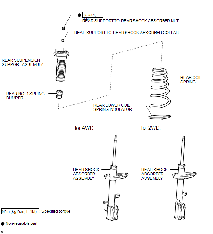
ILLUSTRATION

 Inspection
INSPECTION
PROCEDURE
1. INSPECT REAR SHOCK ABSORBER ASSEMBLY
(a) Compress and extend the shock absorber rod 4 or more times.
Standard:
There is no abnormal resistance or sound and ...
Other materials about Toyota Venza:
Freeze Frame Data
FREEZE FRAME DATA
1. FREEZE FRAME DATA
(a) Whenever an ABS DTC is detected, the skid control ECU stores the current
vehicle (sensor) state as Freeze Frame Data.
(b) The skid control ECU stores the number of times (maximum: 31) the ignition
switch has be ...
Vehicle Speed Signal Error (Test Mode DTC) (C2191/91)
DESCRIPTION
The tire pressure warning ECU receives a vehicle speed signal from the combination
meter. This DTC is stored upon entering signal check mode (test mode), and cleared
when a vehicle speed signal of 20 km/h (12 mph) is detected for 3 seconds or ...
Outside Vehicle
General Maintenance
GENERAL MAINTENANCE
CAUTION / NOTICE / HINT
These are maintenance and inspection items that are considered to be
the owner's responsibility.
The owner can do them or they can have them done at a service center.
The ...

0.1195