Toyota Venza: Components
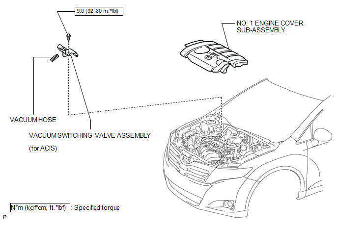
COMPONENTS
ILLUSTRATION
.png)
ILLUSTRATION

 Inspection
INSPECTION
PROCEDURE
1. INSPECT VACUUM SWITCHING VALVE ASSEMBLY (for ACIS)
(a) Measure the resistance according to the value(s) in the table below.
Text in Illustration
...
Other materials about Toyota Venza:
Chassis
General Maintenance
GENERAL MAINTENANCE
PROCEDURE
1. INSPECT STEERING LINKAGE AND GEAR HOUSING
(a) Check the steering wheel free play (See page
).
(b) Check the steering linkage for looseness or damage.
(1) Check that the tie rod ends do not have any ...
Ignition Hold Monitor Malfunction (B2271)
DESCRIPTION
This DTC is stored when a problem such as an open in the AM2 fuse, an open or
short in the wire harness between the fuse and power management control ECU, a short
in the IG output circuit inside the power management control ECU, a short betwee ...
Assist Map Number Un-Writing (C1581)
DESCRIPTION
The power steering ECU stores this DTC when it determines that the assist map
is not written in the ECU.
HINT:
The assist map is data written in the power steering ECU to control the degree
of assistance. The assist map is selected based on ...

0.1388