
Toyota Venza: Components
COMPONENTS
ILLUSTRATION
.png)
ILLUSTRATION
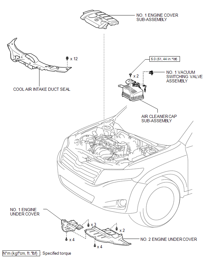
ILLUSTRATION
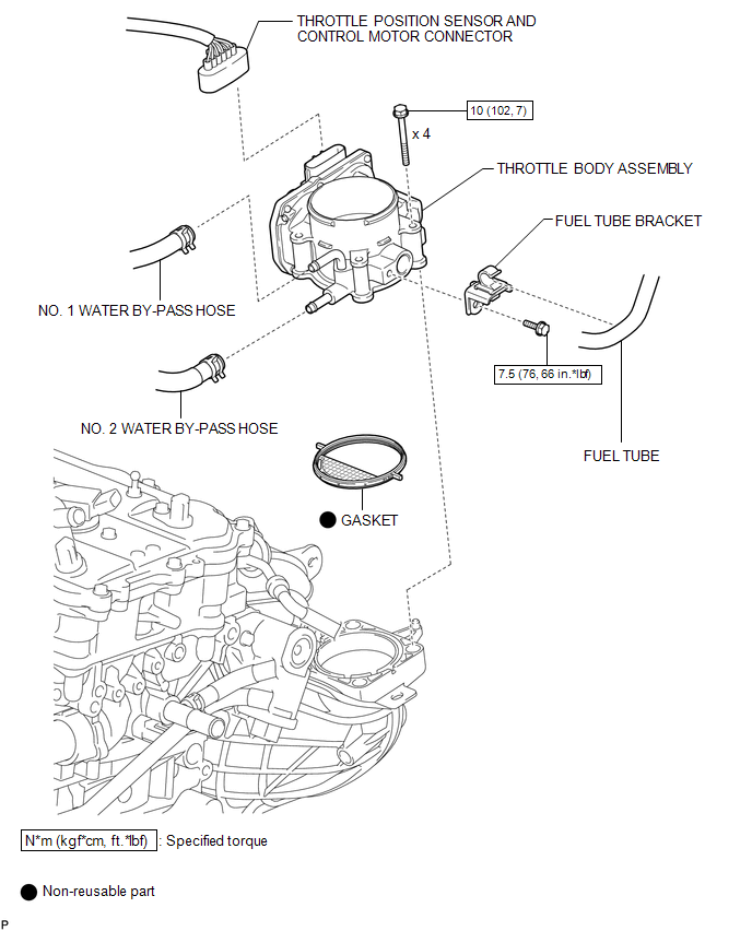
 Throttle Body
...
 On-vehicle Inspection
ON-VEHICLE INSPECTION
PROCEDURE
1. CHECK THROTTLE BODY ASSEMBLY
(a) Check the throttle control motor operating sounds.
(1) Turn the ignition switch to ON.
(2) When pressing the accelerator pedal, ...
Other materials about Toyota Venza:
Components
COMPONENTS
ILLUSTRATION
ILLUSTRATION
ILLUSTRATION
ILLUSTRATION
ILLUSTRATION
ILLUSTRATION
ILLUSTRATION
ILLUSTRATION
ILLUSTRATION
ILLUSTRATION
...
Back Door Courtesy Switch
Components
COMPONENTS
ILLUSTRATION
Removal
REMOVAL
PROCEDURE
1. REMOVE BACK DOOR PANEL TRIM ASSEMBLY
2. REMOVE BACK DOOR LOCK ASSEMBLY
(a) Disconnect the connector.
(b) Disengage the c ...
Precaution
PRECAUTION
1. PRECAUTION FOR DISCONNECTING CABLE FROM NEGATIVE BATTERY TERMINAL
NOTICE:
After the ignition switch is turned off, the radio and display receiver
assembly records various types of memory and settings. As a result, after
turning ...

0.146