Toyota Venza: Clearance Warning Ecu
Components
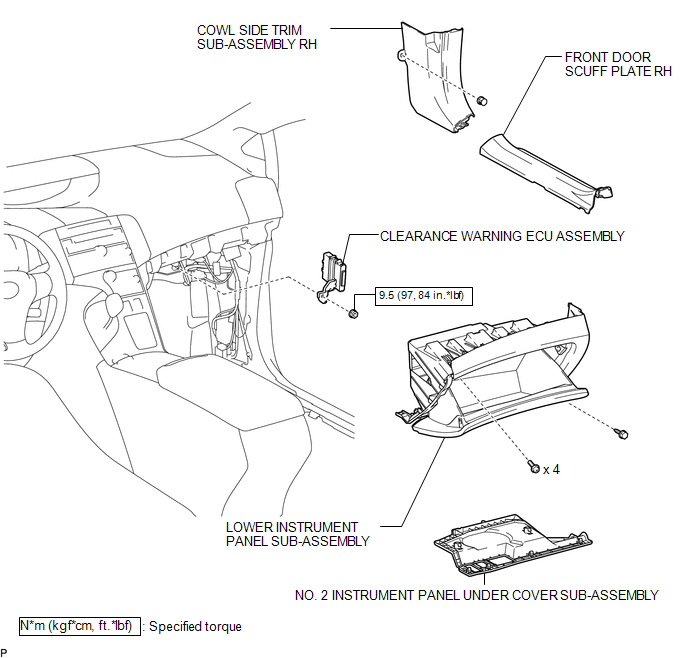
COMPONENTS
ILLUSTRATION
Removal
REMOVAL
PROCEDURE
1. REMOVE FRONT DOOR SCUFF PLATE RH
.gif)
2. REMOVE COWL SIDE TRIM SUB-ASSEMBLY RH
3. REMOVE NO. 2 INSTRUMENT PANEL UNDER COVER SUB-ASSEMBLY
4. REMOVE LOWER INSTRUMENT PANEL SUB-ASSEMBLY
5. REMOVE CLEARANCE WARNING ECU ASSEMBLY
|
(a) Disconnect the connector. |
|
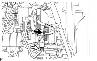
(b) Remove the nut and clearance warning ECU assembly.
Installation
INSTALLATION
PROCEDURE
1. INSTALL CLEARANCE WARNING ECU ASSEMBLY
(a) Install the clearance warning ECU assembly with the nut.
Torque:
9.5 N·m {97 kgf·cm, 84 in·lbf}
(b) Connect the connector.
2. INSTALL LOWER INSTRUMENT PANEL SUB-ASSEMBLY
.gif)
3. INSTALL NO. 2 INSTRUMENT PANEL UNDER COVER SUB-ASSEMBLY
4. INSTALL COWL SIDE TRIM SUB-ASSEMBLY RH
5. INSTALL FRONT DOOR SCUFF PLATE RH
 Clearance Warning Buzzer
Components
COMPONENTS
ILLUSTRATION
Removal
REMOVAL
PROCEDURE
1. REMOVE FRONT DOOR SCUFF PLATE LH
2. REMOVE COWL SIDE TRIM SUB-ASSEMBLY LH
3. REMOVE LOWER NO. 1 INSTRUMENT PANEL FIN ...

Other materials about Toyota Venza:
Main Body ECU Communication Stop Mode
DESCRIPTION
Detection Item
Symptom
Trouble Area
Main Body ECU Communication Stop Mode
"Main Body" is not displayed on "CAN Bus Check" screen of the
Techstream.
...
Steering wheel
The steering wheel can be adjusted to a comfortable position.
Hold the steering wheel and press the lever down.
Adjust to the ideal position by moving the steering wheel horizontally and vertically.
After adjustment, pull the lever up to secure the stee ...
Disassembly
DISASSEMBLY
PROCEDURE
1. REMOVE STEERING RACK BOOT CLIP (for LH Side)
(a) Using pliers, remove the steering rack boot clip.
2. REMOVE STEERING RACK BOOT CLIP (for RH Side)
HINT:
Perform the same procedure as for the LH side.
3. REMOVE NO. 2 STEERING RAC ...

0.1423