Toyota Venza: Clearance Sonar Main Switch
Components
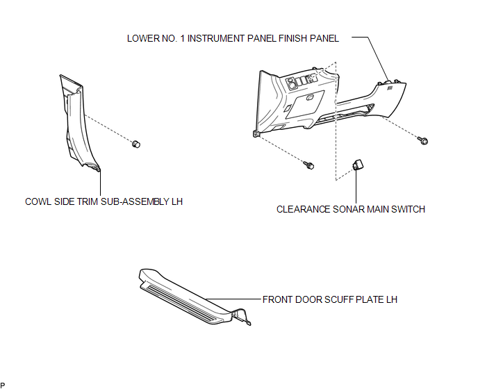
COMPONENTS
ILLUSTRATION
Removal
REMOVAL
PROCEDURE
1. REMOVE FRONT DOOR SCUFF PLATE LH
.gif)
2. REMOVE COWL SIDE TRIM SUB-ASSEMBLY LH
3. REMOVE LOWER NO. 1 INSTRUMENT PANEL FINISH PANEL
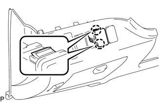
4. REMOVE CLEARANCE SONAR MAIN SWITCH
|
(a) Disengage the 2 claws and remove the clearance sonar main switch. |
|
Inspection
INSPECTION
PROCEDURE
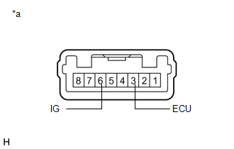
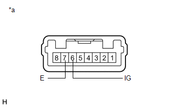
1. INSPECT BACK SONAR OR CLEARANCE SONAR SWITCH ASSEMBLY
|
(a) Measure the resistance according to the value(s) in the table below. Standard Resistance:
If the result is not as specified, replace the back sonar or clearance sonar switch assembly. |
|
(b) Check that the switch illuminates.
|
(1) Apply battery voltage to the back sonar or clearance sonar switch assembly and check that the switch illuminates. OK:
If the result is not as specified, replace the back sonar or clearance sonar switch assembly. |
|
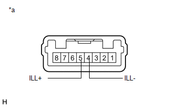
(c) Check switch indicator operation.
|
(1) Apply battery voltage to the back sonar or clearance sonar switch assembly and check that the switch indicator illuminates. OK:
If the result is not as specified, replace the back sonar or clearance sonar switch assembly. |
|
Installation
INSTALLATION
PROCEDURE
1. INSTALL CLEARANCE SONAR MAIN SWITCH
(a) Engage the 2 claws to install the clearance sonar main switch.
2. INSTALL LOWER NO. 1 INSTRUMENT PANEL FINISH PANEL
.gif)
3. INSTALL COWL SIDE TRIM SUB-ASSEMBLY LH
4. INSTALL FRONT DOOR SCUFF PLATE LH

 Clearance Warning Buzzer
Components
COMPONENTS
ILLUSTRATION
Removal
REMOVAL
PROCEDURE
1. REMOVE FRONT DOOR SCUFF PLATE LH
2. REMOVE COWL SIDE TRIM SUB-ASSEMBLY LH
3. REMOVE LOWER NO. 1 INSTRUMENT PANEL FIN ...
Other materials about Toyota Venza:
Precaution
PRECAUTION
NOTICE:
When disconnecting the cable from the negative (-) battery terminal, initialize
the following systems after the cable is reconnected.
System Name
See Procedure
Back Door Closer System
...
Precaution
PRECAUTION
NOTICE:
When the ignition switch is turned off and the engine temperature is
high, the cooling fans may operate for a maximum of 6 minutes.
After turning the ignition switch off, keep hands and objects away from
the fans when t ...
Speaker Circuit
DESCRIPTION
for 6 Speakers:
If there is a short in a speaker circuit, the navigation receiver assembly detects
it and stops output to the speakers.
Thus sound cannot be heard from the speakers even if there is no malfunction
in the navigation receiver a ...

0.1207