Toyota Venza: Center Power Outlet Socket
Components
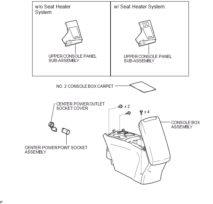
COMPONENTS
ILLUSTRATION
Installation
INSTALLATION
PROCEDURE
1. INSTALL CENTER POWER OUTLET SOCKET COVER
|
(a) Engage the 2 claws to install the center power outlet socket cover. |
|
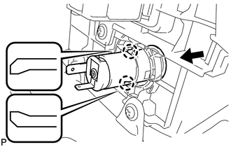
2. INSTALL CENTER POWER POINT SOCKET ASSEMBLY
|
(a) Engage the 2 claws to install the center power point socket assembly as shown in the illustration. |
|
3. INSTALL CONSOLE BOX ASSEMBLY
.gif)
4. INSTALL NO. 2 CONSOLE BOX CARPET
5. INSTALL UPPER CONSOLE PANEL SUB-ASSEMBLY (w/o Seat Heater System)
6. INSTALL UPPER CONSOLE PANEL SUB-ASSEMBLY (w/ Seat Heater System)
Removal
REMOVAL
PROCEDURE
1. REMOVE UPPER CONSOLE PANEL SUB-ASSEMBLY (w/o Seat Heater System)
.gif)
2. REMOVE UPPER CONSOLE PANEL SUB-ASSEMBLY (w/ Seat Heater System)
3. REMOVE NO. 2 CONSOLE BOX CARPET
4. REMOVE CONSOLE BOX ASSEMBLY
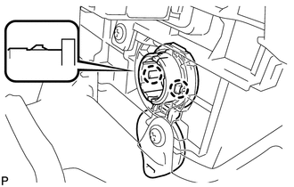
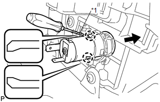
5. REMOVE CENTER POWER POINT SOCKET ASSEMBLY
|
(a) Using a screwdriver, disengage the 2 claws and remove the center power point socket assembly as shown in the illustration. Text in Illustration
HINT: Tape the screwdriver tip before use. |
|
6. REMOVE CENTER POWER OUTLET SOCKET COVER
|
(a) Disengage the 2 claws and remove the center power outlet socket cover. |
|
.png)


Other materials about Toyota Venza:
Initialization
INITIALIZATION
1. INITIALIZE POWER WINDOW CONTROL SYSTEM (POWER WINDOW REGULATOR MOTOR ASSEMBLY
(ALL DOORS))
CAUTION:
When the power window regulator motor assembly is reinstalled or replaced, the
power window control system must be initialized. Functio ...
System Description
SYSTEM DESCRIPTION
1. NAVIGATION SYSTEM OUTLINE
(a) Vehicle position tracking methods
It is essential that the navigation system correctly tracks the current vehicle
position and displays it on the map. There are 2 methods to track the current vehicle
p ...
Cruise Control Input Processor (P1607)
MONITOR DESCRIPTION
The ECM continuously monitors its main and sub CPUs while cruise control is operating.
This self-check ensures that the ECM is functioning properly. If outputs from the
CPUs are different and deviate from the standard, the ECM illumina ...

0.1328