Toyota Venza: Back Door Closer does not Operate
DESCRIPTION
When the back door closer does not operate, one of the following may be the cause: 1) improper fit of the back door, or a foreign object is stuck in the back door or 2) initialization of the power back door ECU (power back door motor unit)*1, or a malfunction in the 3) power back door ECU (power back door motor unit)*1 or back door closer ECU (multiplex network door ECU)*2 power source circuit, 4) back door lock circuit, or 5) power back door ECU (power back door motor unit)*1 or back door closer ECU (multiplex network door ECU)*2.
- *1: w/ Power Back Door System
- *2: w/o Power Back Door System
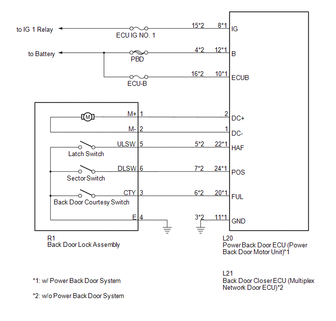
WIRING DIAGRAM
CAUTION / NOTICE / HINT
NOTICE:
Inspect fuses for circuits related to this system before performing the following inspection procedure.
PROCEDURE
|
1. |
CHECK BACK DOOR LOCK FUNCTION |
(a) Check if the back door is fully closed by hand.
|
Result |
Proceed to |
|---|---|
|
OK (w/ Power Back Door System) |
A |
|
OK (w/o Power Back Door System) |
B |
|
NG |
C |
| B | .gif) |
GO TO STEP 5 |
| C | |
IMPROPER FIT OF BACK DOOR, OR A FOREIGN OBJECT IS STUCK IN BACK DOOR |
|
.gif)
|
2. |
INITIALIZE POWER BACK DOOR ECU |
(a) Perform the initialization of the power back door ECU (power back door motor
unit) (See page .gif) ).
).
|
|
3. |
CHECK BACK DOOR CLOSER SYSTEM |
(a) Check back door closer system operation.
OK:
Back door closer system operates normally.
| OK | |
END |
|
|
4. |
READ VALUE USING TECHSTREAM (POWER BACK DOOR TOUCH SENSOR) |
(a) Connect the Techstream to the DLC3.
(b) Turn the ignition switch to ON.
(c) Turn the Techstream on.
(d) Enter the following menus: Body Electrical / Back Door / Data List.
(e) Check the Data List to determine if the power back door touch sensor functions properly.
Back Door (Power Back Door ECU)|
Tester Display |
Measurement Item/Range |
Normal Condition |
Diagnostic Note |
|---|---|---|---|
|
PBD Touch Sensor (Right) |
Power back door touch sensor RH signal / ON or OFF |
ON: Power back door touch sensor RH pressed OFF: Power back door touch sensor RH not pressed |
- |
|
PBD Touch Sensor (Left) |
Power back door touch sensor LH signal / ON or OFF |
ON: Power back door touch sensor LH pressed OFF: Power back door touch sensor LH not pressed |
- |
OK:
The power back door sensors function as specified in the normal condition column.
| NG | |
GO TO OTHER FLOW CHART (TOUCH SENSOR CIRCUIT) |
|
|
5. |
CHECK DTC OUTPUT |
(a) Connect the Techstream to the DLC3.
(b) Turn the ignition switch to ON.
(c) Turn the Techstream on.
(d) Enter the following menus: Body Electrical / Back Door / DTC.
(e) Check for DTCs.
|
Result |
Proceed to |
|---|---|
|
DTC is not output |
A |
|
B2250 is output |
B |
|
B2251 is output |
C |
| B | |
GO TO DTC CHART (B2250) |
| C | |
GO TO DTC CHART (B2251) |
|
|
6. |
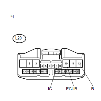
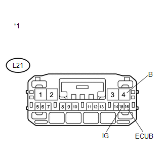
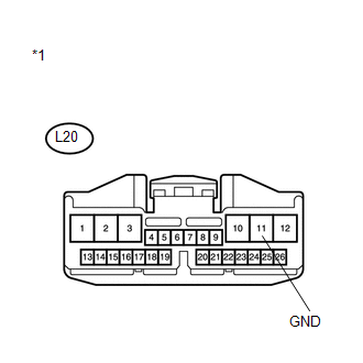
CHECK HARNESS AND CONNECTOR (POWER SOURCE) |
|
(a) w/ Power Back Door System (1) Disconnect the L20 power back door ECU connector. (2) Measure the voltage according to the value(s) in the table below. Standard Voltage:
|
|
|
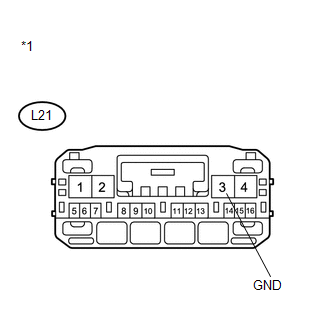
(b) w/o Power Back Door System (1) Disconnect the L21 back door closer ECU connector. (2) Measure the voltage according to the value(s) in the table below. Standard Voltage:
|
|
| NG | |
REPAIR OR REPLACE HARNESS OR CONNECTOR |
|
|
7. |
CHECK HARNESS AND CONNECTOR (BODY GROUND) |
|
(a) w/ Power Back Door System (1) Disconnect the L20 power back door ECU connector. (2) Measure the resistance according to the value(s) in the table below. Standard Resistance:
|
|
|
(b) w/o Power Back Door System (1) Disconnect the L21 back door closer ECU connector. (2) Measure the resistance according to the value(s) in the table below. Standard Resistance:
|
|
| NG | |
REPAIR OR REPLACE HARNESS OR CONNECTOR |
|
|
8. |
INSPECT BACK DOOR LOCK ASSEMBLY |
(a) Remove the back door lock assembly (See page
).
(b) Apply battery voltage and check the operation of the door lock motor.
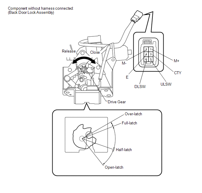
OK:
|
Measurement Condition |
Specified Condition |
|---|---|
|
Battery positive (+) → Terminal 1 (M+) Battery negative (-) → Terminal 2 (M-) |
Latch turns to full-latch position |
|
Battery positive (+) → Terminal 2 (M-) Battery negative (-) → Terminal 1 (M+) |
Latch turns to open-latch position |
(c) Measure the resistance according to the value(s) in the table below.
Standard Resistance:
Latch Switch|
Tester Connection |
Condition |
Specified Condition |
|---|---|---|
|
5 (ULSW) - 4 (E) |
Open-latch |
Below 1 Ω |
|
5 (ULSW) - 4 (E) |
Half-latch |
10 kΩ or higher |
|
5 (ULSW) - 4 (E) |
Full-latch |
10 kΩ or higher |
|
5 (ULSW) - 4 (E) |
Over-latch |
Below 1 Ω |
|
Tester Connection |
Condition |
Specified Condition |
|---|---|---|
|
3 (CTY) - 4 (E) |
Open-latch |
Below 1 Ω |
|
3 (CTY) - 4 (E) |
Half-latch |
Below 1 Ω |
|
3 (CTY) - 4 (E) |
Full-latch |
10 kΩ or higher |
|
3 (CTY) - 4 (E) |
Over-latch |
10 kΩ or higher |
| NG | |
REPLACE BACK DOOR LOCK ASSEMBLY |
|
|
9. |
CHECK HARNESS AND CONNECTOR (BACK DOOR LOCK - POWER BACK DOOR ECU OR BACK DOOR CLOSER ECU) |
(a) w/ Power Back Door System
.png)
(1) Disconnect the R1 back door lock assembly connector and L20 power back door ECU connector.
(2) Measure the resistance according to the value(s) in the table below.
Standard Resistance:
|
Tester Connection |
Condition |
Specified Condition |
|---|---|---|
|
R1-1 (M+) - L20-2 (DC+) |
Always |
Below 1 Ω |
|
R1-2 (M-) - L20-1 (DC-) |
Always |
Below 1 Ω |
|
R1-5 (ULSW) - L20-22 (HAF) |
Always |
Below 1 Ω |
|
R1-6 (DLSW) - L20-24 (POS) |
Always |
Below 1 Ω |
|
R1-3 (CTY) - L20-20 (FUL) |
Always |
Below 1 Ω |
|
R1-4 (E) - Body ground |
Always |
Below 1 Ω |
|
R1-1 (M+) - Body ground |
Always |
10 kΩ or higher |
|
R1-2 (M-) - Body ground |
Always |
10 kΩ or higher |
|
R1-5 (ULSW) - Body ground |
Always |
10 kΩ or higher |
|
R1-6 (DLSW) - Body ground |
Always |
10 kΩ or higher |
|
R1-3 (CTY) - Body ground |
Always |
10 kΩ or higher |
|
*1 |
Front view of wire harness connector (to Back Door Lock) |
|
*2 |
Front view of wire harness connector (to Power Back Door ECU) |
|
(b) w/o Power Back Door System (1) Disconnect the R1 back door lock assembly connector and L21 back door closer ECU connector. (2) Measure the resistance according to the value(s) in the table below. Standard Resistance:
|
|
.png)
|
Result |
Proceed to |
|---|---|
|
NG |
A |
|
OK (w/ Power Back Door System) |
B |
|
OK (w/o Power Back Door System) |
C |
| A | |
REPAIR OR REPLACE HARNESS OR CONNECTOR |
| B | |
REPLACE POWER BACK DOOR ECU (POWER BACK DOOR MOTOR UNIT) |
| C | |
REPLACE BACK DOOR CLOSER ECU (MULTIPLEX NETWORK DOOR ECU) |
 Back Door cannot be Opened
DESCRIPTION
When the back door cannot be opened, one of the following may be malfunctioning:
1) power back door ECU (power back door motor unit)*1 or back door closer ECU (multiplex
network door ...
 Back Door Opener Switch
Components
COMPONENTS
ILLUSTRATION
Removal
REMOVAL
PROCEDURE
1. REMOVE BACK DOOR PANEL TRIM ASSEMBLY
2. REMOVE REAR LIGHT ASSEMBLY LH
3. REMOVE REAR LIGHT ASSEMBLY RH
HINT:
Use t ...
Other materials about Toyota Venza:
Disposal
DISPOSAL
CAUTION / NOTICE / HINT
CAUTION:
Before performing pre-disposal deployment of any SRS component, review and closely
follow all applicable environmental and hazardous material regulations. Pre-disposal
deployment may be considered hazardous mate ...
Power Back Door Warning System does not Operate
DESCRIPTION
When the power back door warning system does not operate, one of the following
may be malfunctioning: 1) power back door warning buzzer circuit, 2) wireless door
lock control system or 3) power back door ECU.
WIRING DIAGRAM
CAUTION / NOTIC ...
System Description
SYSTEM DESCRIPTION
1. LIN COMMUNICATION SYSTEM DESCRIPTION
The LIN communication system is used for communication between the components
in the table below. If communication cannot be performed through LIN communication
because of an open in the communic ...

0.129