Toyota Venza: Automatic door locking and unlocking systems
The following functions can be set or canceled:
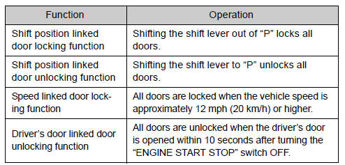
- Setting and canceling the functions
► Setting and canceling the functions Vehicles with TFT type multi-information display The function settings can be changed using the multi-information display.
► Vehicles with LCD type multi-information display To switch between setting and canceling, follow the procedure below:
 Vehicles with smart key system:
Close all the doors and switch the “ENGINE START STOP” switch to IGNITION ON
mode. (Perform  within 20 seconds.)
Vehicles without smart key system:
Close all the doors and switch the engine switch to the “ON” position. (Perform
within 20 seconds.)
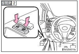
Shift the shift lever to “P” or “N”, press and hold the driver’s door lock switch
(  or
or
 ) for about 5 seconds then release.
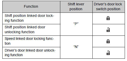
The shift lever and switch positions corresponding to the desired function to be set are shown as follows.
Use the same procedure to cancel the function.
When the setting or canceling operation is complete, all doors are locked and then unlocked.
- Impact detection door lock release system
In the event that the vehicle is subject to a strong impact, all the doors are unlocked.
Depending on the force of the impact or the type of accident, however, the system may not operate.
- Customization
Settings (e.g. unlocking function using a key) can be changed.
(Customizable features )
CAUTION
- To prevent an accident Observe the following precautions while driving the vehicle.
Failing to do so may result in a door opening and an occupant falling out, resulting in death or serious injury.
• Always use a seat belt.
• Always lock all doors.
• Ensure that all doors are properly closed.
• Do not pull the inside handle of the doors while driving.
The doors may be opened and the passengers are thrown out of the vehicle and it may result in death or serious injury.
Be especially careful for the front doors, as the doors may be opened even if the inside lock buttons are in locked position.
• Set the rear door child-protector locks when children are seated in the rear seat.
 Rear door child-protector lock
The door cannot be opened from inside the vehicle when the lock is set.
1. Unlock
2. Lock
These locks can be set to prevent children from opening the rear doors. Push
down on each rear door swi ...
 Back door
The back door can be opened using the back door opener. The back door can
be locked and unlocked using the entry function (vehicles with smart key system),
wireless remote control or door lock swi ...
Other materials about Toyota Venza:
Installation
INSTALLATION
CAUTION / NOTICE / HINT
HINT:
Use the same procedure for the RH side and LH side.
The procedure listed below is for the LH side.
PROCEDURE
1. INSTALL REAR STRUT ROD ASSEMBLY (for 2WD)
(a) Temporarily install the ...
Precaution
PRECAUTION
NOTICE:
When disconnecting the cable from the negative (-) battery terminal, initialize
the following systems after the cable is reconnected.
System Name
See Procedure
Back Door Closer System
...
Theft Deterrent System Presence Detection (B279C)
DESCRIPTION
If an ECM that is incompatible with the engine immobiliser system is installed,
the ECM stores this DTC.
DTC No.
DTC Detection Condition
Trouble Area
B279C
When an ECM that is incompa ...

0.1129