Toyota Venza: Adjustment
ADJUSTMENT
CAUTION / NOTICE / HINT
HINT:
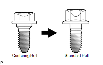
- Centering bolts are used to mount the hood hinge and hood lock. The hood and hood lock cannot be adjusted with the centering bolts installed. Substitute the centering bolts with standard bolts when making adjustments.
- Specified torque for standard bolts is shown in the standard bolt chart
(See page
.gif) ).
).
PROCEDURE
1. REMOVE COOL AIR INTAKE DUCT SEAL
2. REMOVE RADIATOR GRILLE
3. ADJUST HOOD SUB-ASSEMBLY
(a) Horizontally and vertically adjust the hood.
|
(1) Loosen the 4 hinge bolts of the hood. |
|
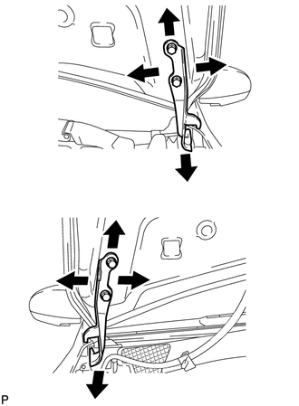
(2) Adjust the clearance between the hood and front fender by moving the hood.
(3) Tighten the 4 hinge bolts after the adjustment.
Torque:
13 N·m {133 kgf·cm, 10 ft·lbf}
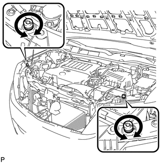
(b) Adjust the height of the front end of the hood using the cushion rubbers.
|
(1) Adjust the 2 cushion rubbers so that the heights of the hood and fender are aligned. HINT: Raise or lower the front end of the hood by turning the 2 cushion rubbers. |
|
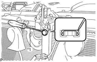
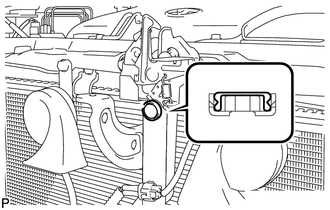
(c) Adjust the hood lock.
|
(1) Using a screwdriver, remove the hood lock nut cap. Text in Illustration
HINT: Tape the screwdriver tip before use. |
|
|
(2) Loosen the 3 bolts. |
|
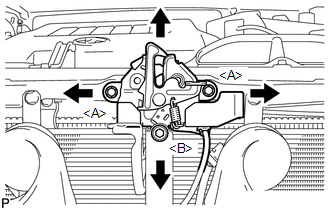
(3) Tighten the bolts after the adjustment.
Torque:
<A> :
7.5 N·m {77 kgf·cm, 66 in·lbf}
Torque:
<B> :
8.0 N·m {82 kgf·cm, 71 in·lbf}
(4) Check that the striker can engage with the hood lock smoothly.
|
(d) Install a new hood lock nut cap. |
|
4. INSTALL RADIATOR GRILLE
5. INSTALL COOL AIR INTAKE DUCT SEAL
 On-vehicle Inspection
ON-VEHICLE INSPECTION
PROCEDURE
1. INSPECT HOOD SUB-ASSEMBLY
(a) Check that the clearance measurements of areas *1 through *4 are within each
standard range.
Standard Clearance
Area ...
 Reassembly
REASSEMBLY
PROCEDURE
1. CONNECT WASHER HOSE ASSEMBLY
(a) Engage the 5 clips and connect the washer hose assembly.
2. INSTALL FRONT WASHER ...
Other materials about Toyota Venza:
Control Module Communication Bus OFF (U0073/86,U0100/85,U0129/83)
DESCRIPTION
The AWD control ECU inputs the signals sent from the ECM and skid control
ECU via the CAN communication system.
When DTCs indicating a CAN communication system malfunction are output,
repair the CAN communication system before r ...
On-vehicle Inspection
ON-VEHICLE INSPECTION
CAUTION / NOTICE / HINT
CAUTION:
Be sure to follow the correct removal and installation procedures of the rear
airbag sensor.
PROCEDURE
1. INSPECT REAR AIRBAG SENSOR (VEHICLE NOT INVOLVED IN COLLISION)
(a) Perform a diagnostic sys ...
Reassembly
REASSEMBLY
PROCEDURE
1. INSTALL BEARING BRACKET HOLE SNAP RING (for RH Side)
(a) Install a new bearing bracket hole snap ring to the front drive shaft assembly
RH.
2. INSTALL FRONT DRIVE SHAFT BEARING (for RH Side)
(a) Using SST, install a ne ...

0.1274