Toyota Venza: On-vehicle Inspection
ON-VEHICLE INSPECTION
PROCEDURE
1. INSPECT HOOD SUB-ASSEMBLY
(a) Check that the clearance measurements of areas *1 through *4 are within each standard range.
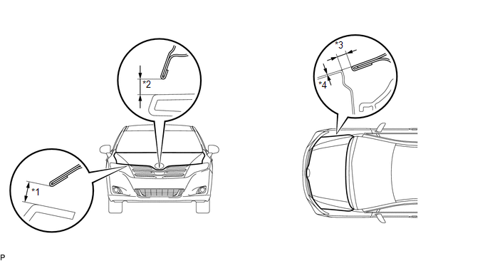 Standard Clearance
|
Area |
Measurement |
Area |
Measurement |
|---|---|---|---|
|
*1 |
6.9 to 9.9 mm (0.272 to 0.390 in.) |
*3 |
2.8 to 5.8 mm (0.110 to 0.228 in.) |
|
*2 |
7.6 to 10.6 mm (0.299 to 0.417 in.) |
*4 |
-1.5 to 1.5 mm (-0.0591 to 0.0591 in.) |
 Disassembly
DISASSEMBLY
PROCEDURE
1. REMOVE HOOD TO RADIATOR SUPPORT SEAL
(a) Using a clip remover, disengage the 10 clips and remove the hood
to radiator support seal.
...
 Adjustment
ADJUSTMENT
CAUTION / NOTICE / HINT
HINT:
Centering bolts are used to mount the hood hinge and hood lock. The
hood and hood lock cannot be adjusted with the centering bolts installed. ...
Other materials about Toyota Venza:
Rear Wheel Alignment
Adjustment
ADJUSTMENT
PROCEDURE
1. INSPECT TIRES
(a) Inspect the tires (See page ).
2. MEASURE VEHICLE HEIGHT
3. INSPECT CAMBER
Camber (Unloaded Vehicle):
Model
Engine
Camber Inclination
Right-left Dif ...
Gauges and meters
►Vehicles with smart key system
The following gauges, meters and display illuminate when the “ENGINE START STOP”
switch is in IGNITION ON mode.
►Vehicles without smart key system
The following gauges, meters and displays illuminate when ...
Diagnostic Trouble Code Chart
DIAGNOSTIC TROUBLE CODE CHART
If a trouble code is displayed during the DTC check, check the trouble areas
listed for that code in the table below and proceed to the appropriate page.
Cruise Control System
DTC Code
Detection Item
...

0.1607