Toyota Venza: Washer Motor(for Rear Side)
Components
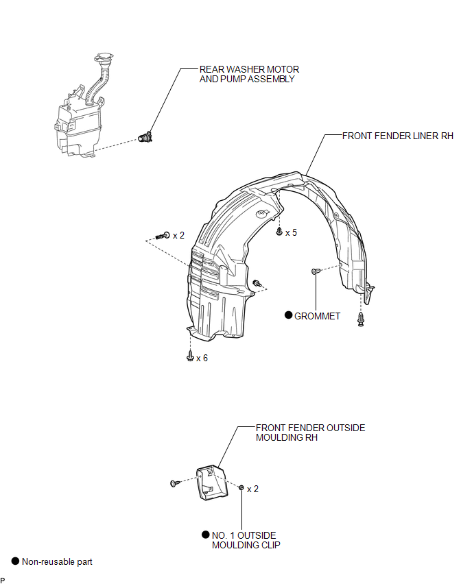
COMPONENTS
ILLUSTRATION
Removal
REMOVAL
PROCEDURE
1. REMOVE FRONT WHEEL RH
2. REMOVE FRONT FENDER OUTSIDE MOULDING RH
HINT:
Use the same procedure for the RH side and LH side (See page
.gif) ).
).
3. REMOVE FRONT FENDER LINER RH
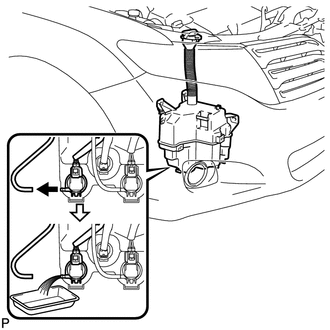
4. DRAIN WINDSHIELD WASHER FLUID
|
(a) Disconnect the washer hose from the rear washer motor and pump assembly, and drain the washer fluid. HINT: Use a container to collect the washer fluid. |
|
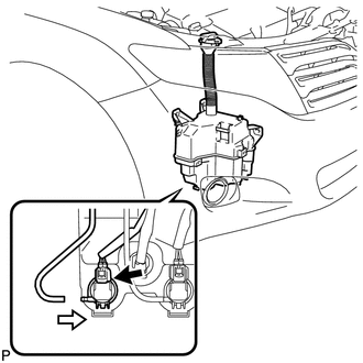
5. REMOVE REAR WASHER MOTOR AND PUMP ASSEMBLY
|
(a) Disconnect the connector. |
|
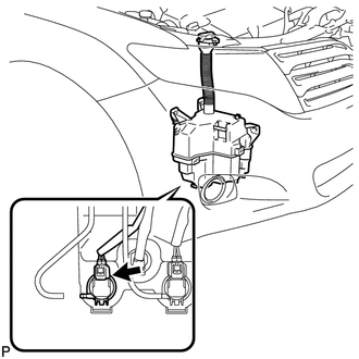
(b) Remove the rear washer motor and pump assembly.
HINT:
Use a container to collect the washer fluid.
Inspection
INSPECTION
PROCEDURE
1. INSPECT REAR WASHER MOTOR AND PUMP ASSEMBLY
(a) Remove the washer jar.
(b) Disconnect the rear washer motor and pump connector.
HINT:
The check should be performed with the rear washer motor and pump installed on the washer jar.
(c) Fill the washer jar with washer fluid.
|
(d) Connect a battery positive (+) lead to terminal 1 of the rear washer motor and pump, and a negative (-) lead to terminal 2. |
|
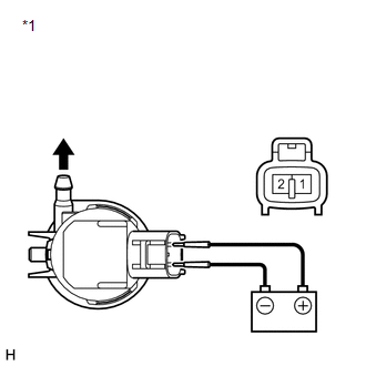
(e) Check that washer fluid flows from the washer jar.
OK:
Washer fluid flows from the washer jar.
If the result is not as specified, replace the rear washer motor and pump assembly.
Text in Illustration|
*1 |
Component without harness connected (Rear Washer Motor and Pump Assembly) |
Installation
INSTALLATION
PROCEDURE
1. INSTALL REAR WASHER MOTOR AND PUMP ASSEMBLY
|
(a) Install the rear washer motor and pump assembly. |
|
(b) Connect the connector.
(c) Connect the washer hose.
2. FILL WASHER JAR WITH WASHER FLUID
(a) Fill the washer jar with washer fluid.
3. INSTALL FRONT FENDER LINER RH
.gif)
4. INSTALL FRONT FENDER OUTSIDE MOULDING RH
HINT:
Use the same procedure for the RH side and LH side (See page
).
5. INSTALL FRONT WHEEL RH
 Washer Motor(for Front Side)
Components
COMPONENTS
ILLUSTRATION
Removal
REMOVAL
PROCEDURE
1. REMOVE FRONT WHEEL RH
2. REMOVE FRONT FENDER OUTSIDE MOULDING RH
HINT:
Use the same procedure for the RH side and LH side ...
 Washer Nozzle(for Front Side)
Components
COMPONENTS
ILLUSTRATION
On-vehicle Inspection
ON-VEHICLE INSPECTION
PROCEDURE
1. INSPECT FRONT WASHER NOZZLE SUB-ASSEMBLY
(a) With the engine running, check that the center str ...
Other materials about Toyota Venza:
Driver Side Door Entry Lock Function does not Operate
DESCRIPTION
If the driver door entry unlock function operates normally, but its entry lock
function does not, this means that the request code from the driver door is being
output normally. In this case, a malfunction in the lock sensor circuit (from the ...
Control Module Performance (P0607)
MONITOR DESCRIPTION
The ECM continuously monitors its internal processors (CPUs) and heated oxygen
sensor transistors. This self-check ensures that the ECM is functioning properly.
DTC No.
DTC Detection Condition
Trouble Ar ...
Internal Control Module Monitoring Processor Performance (P060A)
MONITOR DESCRIPTION
The main CPU and sub CPU of the ECM perform data communication between each other.
The main CPU monitors the communications and WDC pulses from the sub CPU. When the
signal malfunctions below are detected, the DTC is output.
...

0.1681