Toyota Venza: Washer Motor(for Front Side)
Components
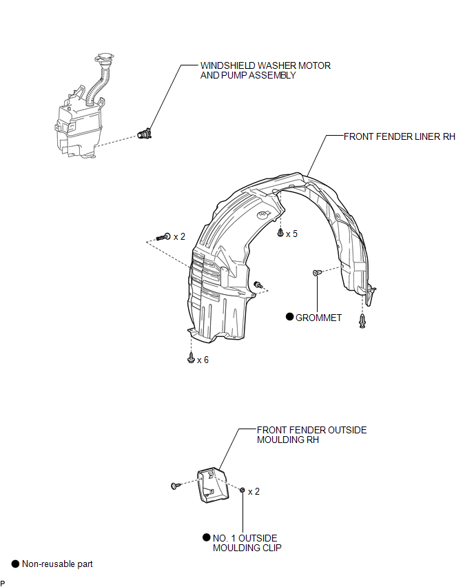
COMPONENTS
ILLUSTRATION
Removal
REMOVAL
PROCEDURE
1. REMOVE FRONT WHEEL RH
2. REMOVE FRONT FENDER OUTSIDE MOULDING RH
HINT:
Use the same procedure for the RH side and LH side (See page
.gif) ).
).
3. REMOVE FRONT FENDER LINER RH
|
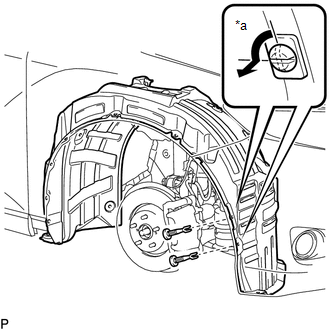
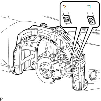
(a) Using a screwdriver, turn the pin 90 degrees and remove the 2 pin hold clips. Text in Illustration
|
|
|
(b) Remove the 5 clips <A>. Text in Illustration
|
|
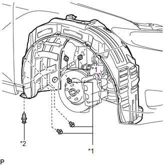
(c) Remove the clip <B>.
|
(d) Remove the bolt and 6 screws. |
|
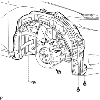
(e) Remove the grommet and front fender liner RH.
HINT:
The grommet need to be replaced with new ones because they will break when they are removed.
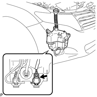
4. DRAIN WINDSHIELD WASHER FLUID
|
(a) Disconnect the washer hose from the windshield washer motor and pump assembly, and drain the washer fluid. HINT: Use a container to collect the washer fluid. |
|
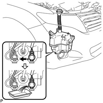
5. REMOVE WINDSHIELD WASHER MOTOR AND PUMP ASSEMBLY
|
(a) Disconnect the connector. |
|
(b) Remove the windshield washer motor and pump assembly.
HINT:
Use a container to collect the washer fluid.
Inspection
INSPECTION
PROCEDURE
1. INSPECT WINDSHIELD WASHER MOTOR AND PUMP ASSEMBLY
(a) Remove the washer jar.
(b) Disconnect the windshield washer motor and pump connector.
HINT:
The check should be performed with the windshield washer motor and pump installed on the washer jar.
(c) Fill the washer jar with washer fluid.
|
(d) Connect a battery positive (+) lead to terminal 1 of the windshield washer motor and pump, and a negative (-) lead to terminal 2. |
|
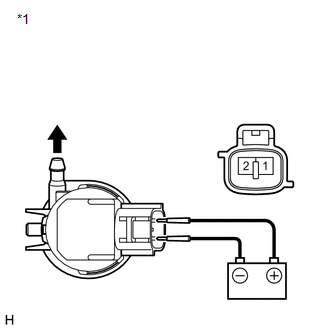
(e) Check that washer fluid flows from the washer jar.
OK:
Washer fluid flows from the washer jar.
If the result is not as specified, replace the windshield washer motor and pump assembly.
Text in Illustration|
*1 |
Component without harness connected (Windshield Washer Motor and Pump Assembly) |
Installation
INSTALLATION
PROCEDURE
1. INSTALL WINDSHIELD WASHER MOTOR AND PUMP ASSEMBLY
|
(a) Install the windshield washer motor and pump assembly. |
|
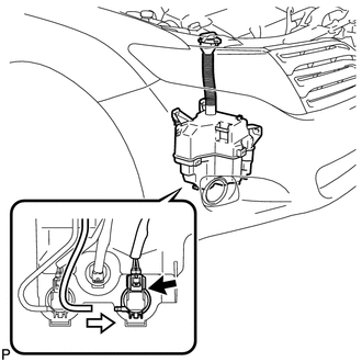
(b) Connect the connector.
(c) Connect the washer hose.
2. FILL WASHER JAR WITH WASHER FLUID
(a) Fill the washer jar with washer fluid.
3. INSTALL FRONT FENDER LINER RH
(a) Install the front fender liner RH with a new grommet.
(b) Install the 5 clips <A>.
(c) Install the clip <B>.
(d) Install the bolt and 6 screws.
|
(e) Install the 2 pin hold clips. Text in Illustration
NOTICE: Insert the pin hold with the slot aligned vertically. Do not rotate the clip after inserting it. After installation, confirm that the slot is aligned vertically. |
|
4. INSTALL FRONT FENDER OUTSIDE MOULDING RH
HINT:
Use the same procedure for the RH side and LH side (See page
.gif) ).
).
5. INSTALL FRONT WHEEL RH
 Washer Level Warning Switch
Components
COMPONENTS
ILLUSTRATION
Inspection
INSPECTION
PROCEDURE
1. INSPECT LEVEL WARNING SWITCH ASSEMBLY
HINT:
The following check should be performed with the windshield washer motor ...
 Washer Motor(for Rear Side)
Components
COMPONENTS
ILLUSTRATION
Removal
REMOVAL
PROCEDURE
1. REMOVE FRONT WHEEL RH
2. REMOVE FRONT FENDER OUTSIDE MOULDING RH
HINT:
Use the same procedure for the RH side and LH side ...
Other materials about Toyota Venza:
Cruise Control Main Switch
Components
COMPONENTS
ILLUSTRATION
Removal
REMOVAL
PROCEDURE
1. REMOVE STEERING PAD
(See page )
2. REMOVE CRUISE CONTROL MAIN SWITCH
(a) Remove the 2 screws.
(b) Disconnect t ...
Low Battery Positive Voltage or Abnormally High Battery Positive Voltage (C1241/41)
DESCRIPTION
If a malfunction is detected in the power supply circuit, the skid control ECU
(housed in the actuator assembly) stores this DTC and the fail-safe function prohibits
ABS operation.
This DTC is stored when the IG1 terminal voltage deviates fro ...
Installation
INSTALLATION
PROCEDURE
1. INSTALL ROOF HEADLINING ASSEMBLY (w/o Sliding Roof)
(a) Pull the roof headlining assembly into the vehicle through the back
door.
NOTICE:
Do not damage the roof headlining assembly or body interior.
...

0.1484