Toyota Venza: Removal
REMOVAL
CAUTION / NOTICE / HINT
HINT:
- Use the same procedure for the LH side and RH side.
- The following procedure listed below is for the LH side.
PROCEDURE
1. REMOVE REAR WHEEL
2. SEPARATE REAR SPEED SENSOR
.gif)
3. REMOVE REAR AXLE SHAFT NUT
|
(a) Using SST and a hammer, release the staked part of the rear axle shaft nut. SST: 09930-00010 NOTICE: Loosen the staked part of the nut completely, otherwise the threads of the drive shaft may be damaged. |
|
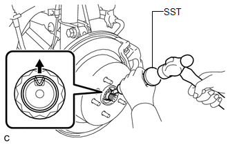
(b) While applying the brakes, remove the rear axle shaft nut.
4. SEPARATE REAR DISC BRAKE CALIPER ASSEMBLY
5. REMOVE REAR DISC
6. REMOVE REAR AXLE HUB AND BEARING ASSEMBLY
7. SEPARATE NO. 3 PARKING BRAKE CABLE ASSEMBLY
8. REMOVE REAR STRUT ROD ASSEMBLY
9. REMOVE REAR AXLE CARRIER SUB-ASSEMBLY
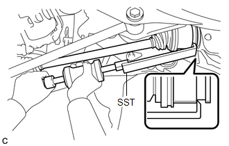
10. REMOVE REAR DRIVE SHAFT ASSEMBLY
|
(a) Using SST, remove the rear drive shaft assembly as shown in the illustration. SST: 09520-01010 SST: 09520-24010 09520-32040 NOTICE: Remove the rear drive shaft assembly while keeping it level. |
|
 Components
COMPONENTS
ILLUSTRATION
ILLUSTRATION
...
 Disassembly
DISASSEMBLY
PROCEDURE
1. REMOVE REAR DRIVE SHAFT SNAP RING
(a) Using a screwdriver, remove the rear drive shaft snap ring.
2. REMOVE NO. 2 ...
Other materials about Toyota Venza:
Speaker Circuit
DESCRIPTION
for 6 Speakers:
If there is a short in a speaker circuit, the navigation receiver assembly detects
it and stops output to the speakers.
Thus sound cannot be heard from the speakers even if there is no malfunction
in the navigation receiver a ...
Noise Occurs from Generator while Engine is Running
PROCEDURE
1.
CHECK LOOSENESS OF V-RIBBED BELT
(a) Check the tension of the belt by pushing it down with a finger.
OK:
The tension of the belt is enough.
NG
ADJUST V-RIBBED BELT
...
Power Source Circuit
DESCRIPTION
This circuit supplies power source voltage from the battery to terminal B of
the steering lock ECU (steering lock actuator assembly). This is used as power source
for the CPU, motor, communication, and peripheral circuits.
WIRING DIAGRAM
P ...

0.1275