Toyota Venza: Cruise Control Main Switch
Components
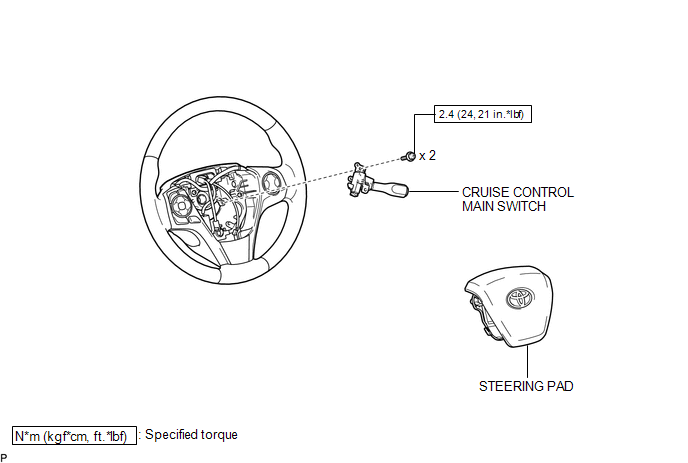
COMPONENTS
ILLUSTRATION
Removal
REMOVAL
PROCEDURE
1. REMOVE STEERING PAD
(See page .gif) )
)
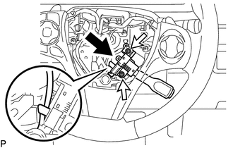
2. REMOVE CRUISE CONTROL MAIN SWITCH
|
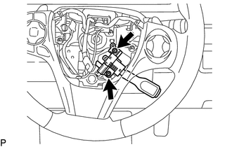
(a) Remove the 2 screws. |
|
|
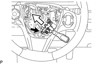
(b) Disconnect the connector and remove the cruise control main switch shown in the illustration. |
|
Inspection
INSPECTION
PROCEDURE
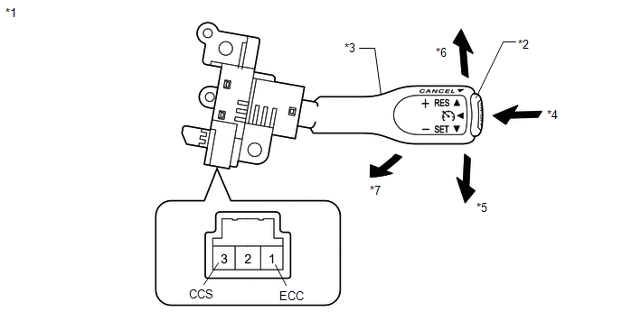
1. INSPECT CRUISE CONTROL MAIN SWITCH
(a) for vehicles without vehicle-to-vehicle distance control mode:
(1) Measure the resistance according to the value(s) in the table below.
 Text in Illustration
|
*1 |
Component without harness connected: (Cruise Control Main Switch) |
*2 |
Main Switch |
|
*3 |
Lever |
*4 |
ON/OFF |
|
*5 |
- SET |
*6 |
+ RES |
|
*7 |
CANCEL |
- |
- |
Standard Resistance:
|
Tester Connection |
Switch Condition |
Specified Condition |
|---|---|---|
|
1 (ECC) - 3 (CCS) |
Main Switch off*1 |
1 MΩ or higher |
|
Main Switch on |
Below 2.5 Ω |
|
|
+ RES |
235 to 245 Ω |
|
|
- SET |
617 to 643 Ω |
|
|
CANCEL |
1509 to 1571 Ω |
*1: Lever is in neutral position
If the result is not as specified, replace the cruise control main switch.
Installation
INSTALLATION
PROCEDURE
1. INSTALL CRUISE CONTROL MAIN SWITCH
(a) Connect the connector.
|
(b) Install the cruise control main switch with the 2 screws shown in the illustration. Torque: 2.4 N·m {24 kgf·cm, 21 in·lbf} |
|
2. INSTALL STEERING PAD
(See page .gif) )
)
 Cruise Control
...

Other materials about Toyota Venza:
Slide Sensor Malfunction (B2650)
DESCRIPTION
When the position control ECU and switch assembly does not receive a sensor signal
despite forward or backward movement of seat by power seat motor operation, this
DTC is output.
DTC Code
DTC Detection Condition
...
Installation
INSTALLATION
PROCEDURE
1. INSTALL REAR DRIVE SHAFT ASSEMBLY
(a) Align the shaft splines and install the rear drive shaft assembly
using a screwdriver and hammer.
NOTICE:
Set the snap ring with the opening facing downward.
...
Customize Parameters
CUSTOMIZE PARAMETERS
HINT:
The following items can be customized.
NOTICE:
After confirming whether the items requested by the customer are applicable
or not for customization, perform customizing operations.
Be sure to record the current se ...

0.136