Toyota Venza: Washer Level Warning Switch
Components
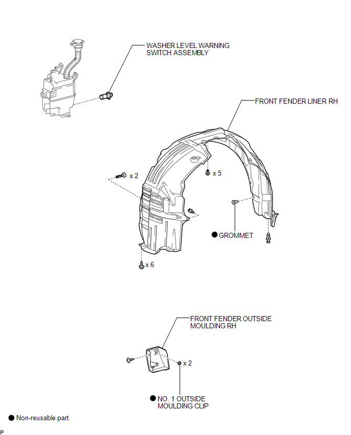
COMPONENTS
ILLUSTRATION
Inspection
INSPECTION
PROCEDURE
1. INSPECT LEVEL WARNING SWITCH ASSEMBLY
HINT:
The following check should be performed with the windshield washer motor and pump installed to the washer jar.
(a) Fill the washer jar with washer fluid.
|
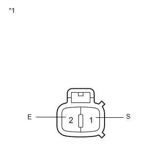
(b) Measure the resistance according to the value(s) in the table below. Standard Resistance:
If the result is not as specified, replace the level warning switch assembly. Text in Illustration
|
|
Removal
REMOVAL
PROCEDURE
1. REMOVE FRONT WHEEL RH
2. REMOVE FRONT FENDER OUTSIDE MOULDING RH
HINT:
Use the same procedure for the RH side and LH side (See page
.gif) ).
).
3. REMOVE FRONT FENDER LINER RH
4. DRAIN WINDSHIELD WASHER FLUID
5. REMOVE WASHER LEVEL WARNING SWITCH ASSEMBLY
|
(a) Disconnect the connector. |
|
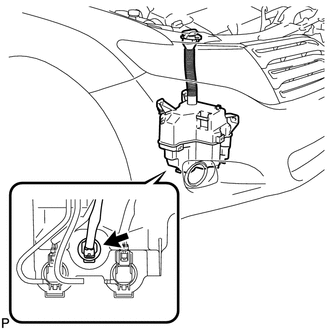
(b) Remove the washer level warning switch assembly.
Installation
INSTALLATION
PROCEDURE
1. INSTALL WASHER LEVEL WARNING SWITCH ASSEMBLY
|
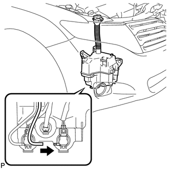
(a) Install the washer level warning switch assembly. |
|
.png)
(b) Connect the connector.
|
(c) Connect the washer hose. |
|
2. FILL WASHER JAR WITH WASHER FLUID
.gif)
3. INSTALL FRONT FENDER LINER RH
4. INSTALL FRONT FENDER OUTSIDE MOULDING RH
HINT:
Use the same procedure for the RH side and LH side (See page
).
5. INSTALL FRONT WHEEL RH
 Rear Wiper Rubber
Components
COMPONENTS
ILLUSTRATION
Replacement
REPLACEMENT
PROCEDURE
1. REMOVE REAR WIPER BLADE
(a) Disconnect the rear wiper arm head cap.
...
 Washer Motor(for Front Side)
Components
COMPONENTS
ILLUSTRATION
Removal
REMOVAL
PROCEDURE
1. REMOVE FRONT WHEEL RH
2. REMOVE FRONT FENDER OUTSIDE MOULDING RH
HINT:
Use the same procedure for the RH side and LH side ...
Other materials about Toyota Venza:
No Sound can be Heard from Speakers
PROCEDURE
1.
CHECK AUDIO SETTINGS
(a) In sound output setting mode, set volume, fader and balance to the initial
values and check that the sound is normal.
OK:
Audio system returns to normal.
HINT:
Sound quality adjustm ...
All Doors LOCK/UNLOCK Functions do not Operate Via Door Control Switch
DESCRIPTION
The main body ECU (driver side junction block assembly) receives switch signals
from the door control switch and activates the door lock motor on each door according
to these signals.
WIRING DIAGRAM
PROCEDURE
1.
REA ...
On-vehicle Inspection
ON-VEHICLE INSPECTION
PROCEDURE
1. INSPECT PARK/NEUTRAL POSITION SWITCH ASSEMBLY OPERATION
(a) Apply the parking brake.
(b) Turn the ignition switch to ON.
(c) Depress the brake pedal and check that the engine starts when the shift lever
is in N or P, b ...

0.1155