Toyota Venza: Rear Wiper Rubber
Components
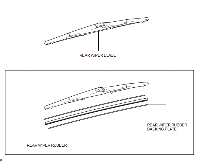
COMPONENTS
ILLUSTRATION
Replacement
REPLACEMENT
PROCEDURE
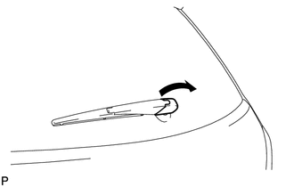
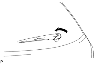
1. REMOVE REAR WIPER BLADE
|
(a) Disconnect the rear wiper arm head cap. |
|
|
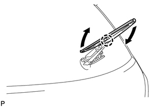
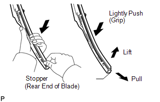
(b) Raise the wiper blade to the position where the claw detaches with a click sound, as shown in the illustration. NOTICE: Be careful not to damage the claw. |
|
|
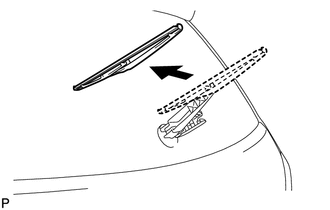
(c) Pull the wiper blade straight toward the left side of the vehicle to remove it from the wiper arm. NOTICE: Do not lower the wiper arm with the wiper blade removed. The arm tip may damage the back door glass surface. |
|
2. REMOVE REAR WIPER RUBBER
|
(a) Lift and pull the end of the wiper rubber protrusion from the blade stopper as shown in the illustration. NOTICE: Do not forcibly pull out the wiper rubber. The backing plates will be deformed or the blade claws will be damaged. HINT: Lightly pushing the rubber in the middle will allow it to be removed more easily. |
|
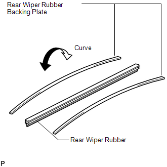
(b) Remove the rear wiper rubber backing plates.
3. INSTALL REAR WIPER RUBBER
|
(a) Install the rear wiper rubber backing plates as shown in the illustration. NOTICE: Install the backing plates facing the correct direction. |
|
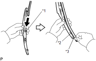
(b) Insert the wiper rubber from the front end of the wiper blade to the rear end through the second claw.
|
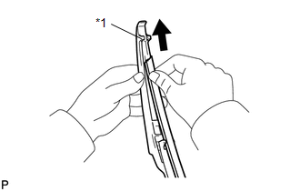
(c) After pushing the wiper rubber through the rear end claw, allow it to stick out from the rear end stopper. Text in Illustration
|
|
|
(d) Slide the wiper rubber through the front end claw. Text in Illustration
|
|
4. INSTALL REAR WIPER BLADE
|
(a) Push the wiper blade straight toward the right side of the vehicle to install it to the wiper arm. NOTICE: Be careful not to damage the claw. |
|

|
(b) Connect the rear wiper head cap. |
|
 Installation
INSTALLATION
PROCEDURE
1. INSTALL REAR WIPER MOTOR AND BRACKET ASSEMBLY
(a) Install the rear wiper motor and bracket assembly with the 3 bolts.
Torque:
5.5 N·m {56 kgf·cm, 49 in ...
 Washer Level Warning Switch
Components
COMPONENTS
ILLUSTRATION
Inspection
INSPECTION
PROCEDURE
1. INSPECT LEVEL WARNING SWITCH ASSEMBLY
HINT:
The following check should be performed with the windshield washer motor ...
Other materials about Toyota Venza:
Transponder Chip Malfunction (B2793)
DESCRIPTION
This DTC is stored when a malfunction is found in the key during key code registration
or a key code is not registered normally. Replace the key if the key code registration
is not performed normally and this DTC is detected.
DTC N ...
Installation
INSTALLATION
PROCEDURE
1. INSTALL REAR SEAT OUTER BELT ASSEMBLY
(a) Engage the 2 guides.
(b) Install the rear seat outer belt assembly with the 2 bolts.
Torque:
Bolt <A> :
7.5 N·m {77 kg ...
Precaution
PRECAUTION
NOTICE:
When disconnecting the cable from the negative (-) battery terminal, initialize
the following systems after the cable is reconnected.
System Name
See Procedure
Back Door Closer System
...

0.1445