
Toyota Venza: Installation
INSTALLATION
PROCEDURE
1. INSTALL WINDSHIELD WIPER MOTOR ASSEMBLY
|
(a) Using a T30 "TORX" socket wrench, install the windshield wiper motor assembly with the 2 bolts. Torque: 7.5 N·m {76 kgf·cm, 66 in·lbf} |
|
.png)
(b) Apply MP grease to the crank arm pivot of the windshield wiper motor assembly.
|
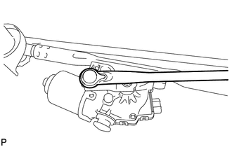
(c) Install the windshield wiper link rod to the crank arm pivot of the windshield wiper motor assembly. |
|
2. INSTALL WINDSHIELD WIPER MOTOR AND LINK ASSEMBLY
|
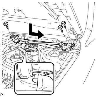
(a) Install the windshield wiper motor and link assembly with the 3 bolts as shown in the illustration. Torque: 7.0 N·m {71 kgf·cm, 62 in·lbf} |
|
|
(b) Connect the connector. |
|
.png)
3. INSTALL COWL TOP VENTILATOR LOUVER SUB-ASSEMBLY
|
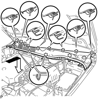
(a) Engage the 13 claws and install the cowl top ventilator louver sub-assembly as shown in the illustration. |
|
|
(b) Install the 2 clips. |
|
.png)
4. INSTALL FRONT FENDER TO COWL SIDE SEAL LH
|
(a) Engage the claw and 2 guides to install the front fender to cowl side seal LH. |
|
.png)
5. INSTALL FRONT FENDER TO COWL SIDE SEAL RH
HINT:
Use the same procedure for the RH side and LH side.
6. INSTALL FRONT WIPER ARM AND BLADE ASSEMBLY RH
(a) Operate the wiper and stop the windshield wiper motor at the automatic stop position.
(b) When reusing the front wiper arm and blade assembly RH:
|
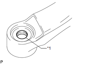
(1) Clean the wiper arm serrations. Text in Illustration
|
|
(c) When reusing the windshield wiper link assembly:
|
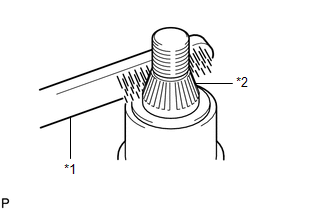
(1) Clean the wiper pivot serrations with a wire brush. Text in Illustration
|
|
|
(d) Install the front wiper arm and blade assembly RH with the nut to the position shown in the illustration. Text in Illustration
Torque: 20 N·m {204 kgf·cm, 15 ft·lbf} |
|
.png)
7. INSTALL FRONT WIPER ARM AND BLADE ASSEMBLY LH
(a) When reusing the front wiper arm and blade assembly LH:
|
(1) Clean the wiper arm serrations. Text in Illustration
|
|
(b) When reusing the windshield wiper link assembly:
|
(1) Clean the wiper pivot serrations with a wire brush. Text in Illustration
|
|
|
(c) Install the front wiper arm and blade assembly LH with the nut to the position shown in the illustration. Text in Illustration
Torque: 20 N·m {204 kgf·cm, 15 ft·lbf} |
|
.png)
(d) Operate the front wipers while spraying washer fluid onto the windshield. Make sure that the front wipers function properly and the wipers do not come into contact with the vehicle body.
8. INSTALL FRONT WIPER ARM HEAD CAP
|
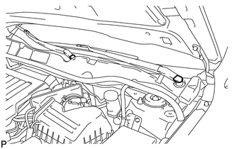
(a) Install the 2 front wiper arm head caps. |
|
 Removal
REMOVAL
PROCEDURE
1. REMOVE FRONT WIPER ARM HEAD CAP
(a) Using a screwdriver, remove the 2 front wiper arm head caps as shown
in the illustration.
Text in Illustration
...
 Front Wiper Rubber
Components
COMPONENTS
ILLUSTRATION
Replacement
REPLACEMENT
PROCEDURE
1. REMOVE FRONT WIPER BLADE
(a) Remove the holder of the front wiper blade.
...
Other materials about Toyota Venza:
System Description
SYSTEM DESCRIPTION
1. FUNCTION DESCRIPTION
(a) Steering Cooperative Control
(1) Enhanced-VSC performs coordinated control consisting of VSC and electronic
power steering. By integrating these preventive safety functions, Enhanced-VSC ensures
excellent d ...
ECU Power Source Circuit
DESCRIPTION
This circuit provides power for main body ECU (driver side junction block assembly)
operation.
WIRING DIAGRAM
PROCEDURE
1.
CHECK DRIVER SIDE JUNCTION BLOCK ASSEMBLY (MAIN BODY ECU (POWER SOURCE))
...
Installation
INSTALLATION
PROCEDURE
1. INSTALL INNER REAR VIEW MIRROR ASSEMBLY (w/o Automatic High Beam System)
(a) Using a T20 "TORX" socket wrench, install the inner rear view mirror assembly
with the screw.
Torque:
1.5 N·m {15 kgf·cm, 13 in·lbf}
(b ...

0.1287