Toyota Venza: Vanity Light
Components
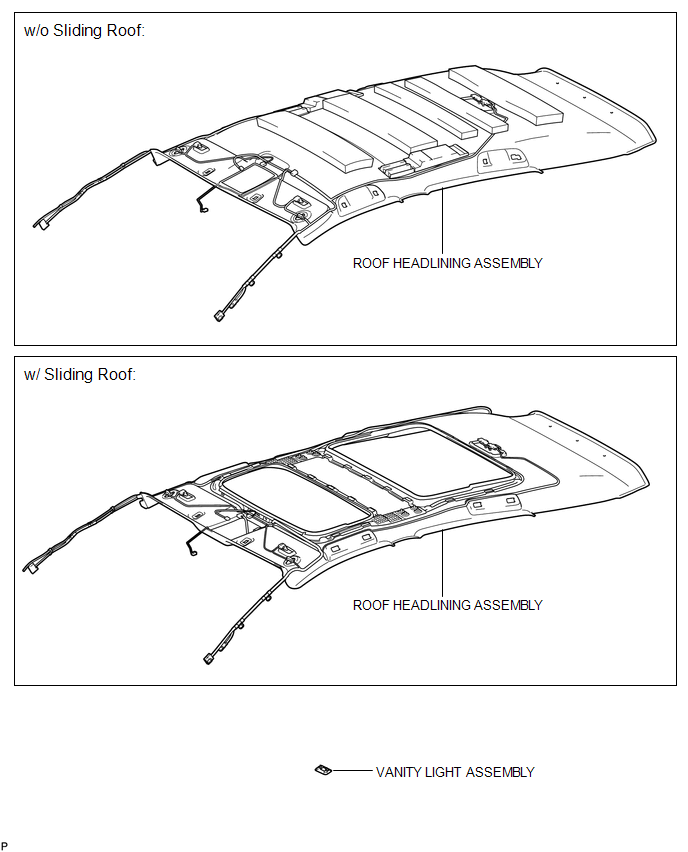
COMPONENTS
ILLUSTRATION
Installation
INSTALLATION
PROCEDURE
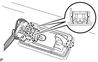
1. INSTALL VANITY LIGHT ASSEMBLY
|
(a) Engage the 3 claws and install the vanity light assembly. |
|
2. INSTALL ROOF HEADLINING ASSEMBLY
HINT:
Refer to the procedure from Install Roof Headlining Assembly (See page
.gif) ).
).
Removal
REMOVAL
PROCEDURE
1. REMOVE ROOF HEADLINING ASSEMBLY
HINT:
Refer to the procedure up to Remove Roof Headlining Assembly (See page
.gif) ).
).
2. REMOVE VANITY LIGHT ASSEMBLY
|
(a) Tilt the tab to disengage the 2 claws <A> and separate the bulb holder from the vanity light, as shown in the illustration. Text in Illustration
|
|
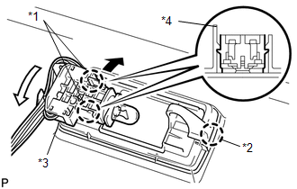
(b) Disengage the claw <B> and remove the vanity light assembly.
 Room Light
Components
COMPONENTS
ILLUSTRATION
Removal
REMOVAL
PROCEDURE
1. REMOVE SPOT LIGHT ASSEMBLY
(a) Using a screwdriver with its tip wrapped with protective tape, disengage
the ...

Other materials about Toyota Venza:
Parking Brake Switch Circuit
DESCRIPTION
The main body ECU (driver side junction block assembly) detects the condition
of the parking brake switch.
WIRING DIAGRAM
PROCEDURE
1.
READ VALUE USING TECHSTREAM
(a) Connect the Techstream to the DLC3.
(b) ...
Occupant Classification System Malfunction (B1650/32)
DESCRIPTION
The occupant classification system circuit consists of the center airbag sensor
assembly and occupant classification system.
If the center airbag sensor assembly receives signals from the occupant classification
ECU, it determines whether the ...
Initialization
INITIALIZATION
NOTICE:
Initialize the headlight leveling ECU assembly (set the zero point of
the height control sensor in the headlight leveling ECU assembly) after
the vehicle height changes due to replacement of the suspension or after
...

0.1149