Toyota Venza: Ultrasonic Sensor(for Front Side)
Components
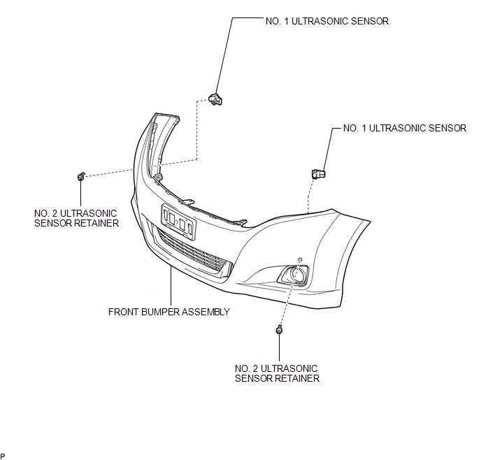
COMPONENTS
ILLUSTRATION
Removal
REMOVAL
PROCEDURE
1. REMOVE FRONT BUMPER ASSEMBLY
(See page .gif) )
)
2. REMOVE NO. 1 ULTRASONIC SENSOR
|
(a) Disengage the 2 claws to remove the No. 1 ultrasonic sensor. HINT: Use the same procedure for the RH side and LH side. |
|
3. REMOVE NO. 2 ULTRASONIC SENSOR RETAINER
|
(a) Disengage the 2 claws to remove the No. 2 ultrasonic sensor retainer from the front bumper assembly. HINT: Use the same procedure for the RH side and LH side. |
|
Inspection
INSPECTION
PROCEDURE
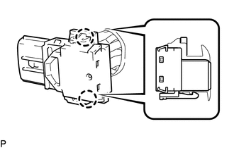
1. INSPECT NO. 1 ULTRASONIC SENSOR
|
(a) Measure the resistance according to the value(s) in the table below. Standard Resistance:
If the result is not as specified, replace the No. 1 ultrasonic sensor. |
|
.png)
Installation
INSTALLATION
PROCEDURE
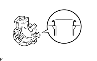
1. INSTALL NO. 2 ULTRASONIC SENSOR RETAINER
|
(a) Engage the 2 claws to install the No. 2 ultrasonic sensor retainer to the front bumper assembly. Text in Illustration
NOTICE:
HINT:
|
|
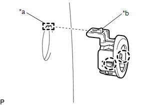
2. INSTALL NO. 1 ULTRASONIC SENSOR
(a) Engage the 2 claws to install the No. 1 ultrasonic sensor to the No. 2 ultrasonic sensor retainer.
NOTICE:
Push the No. 2 ultrasonic sensor retainer from the outside of the front bumper assembly when there is a gap between the No. 2 ultrasonic sensor retainer and the front bumper assembly surface. In this case, do not push on the No. 1ultrasonic sensor.
HINT:
Use the same procedure for the RH side and LH side.
3. INSTALL FRONT BUMPER ASSEMBLY
(See page .gif) )
)
 Television Camera
Components
COMPONENTS
ILLUSTRATION
ILLUSTRATION
Removal
REMOVAL
PROCEDURE
1. REMOVE BACK DOOR PANEL TRIM ASSEMBLY
2. REMOVE REAR WIPER ARM HEAD CAP
3. REMOVE REAR WIPER ARM AND ...

Other materials about Toyota Venza:
Using a flat bed truck
If you use chains or cables to tie down your vehicle, the angles shaded in black
must be 45°.
Do not overly tighten the tie downs or the vehicle may be damaged.
NOTICE
- To prevent body damage when towing a sling-type truck
Do not tow with a sli ...
System Description
SYSTEM DESCRIPTION
1. FRONT POWER SEAT CONTROL SYSTEM DESCRIPTION
The driver seat is equipped with slide, reclining, lifter, front vertical and
lumbar support adjustment functions.
2. FUNCTION OF MAIN COMPONENTS
The following functions are available:
...
Removal
REMOVAL
CAUTION / NOTICE / HINT
CAUTION:
Wear protective gloves when removing the exhaust pipe.
The exhaust pipe is extremely hot immediately after the engine has stopped.
Confirm that the exhaust pipe has cooled down ...

0.1476