Toyota Venza: Television Camera
Components
COMPONENTS
ILLUSTRATION
ILLUSTRATION
Removal
REMOVAL
PROCEDURE
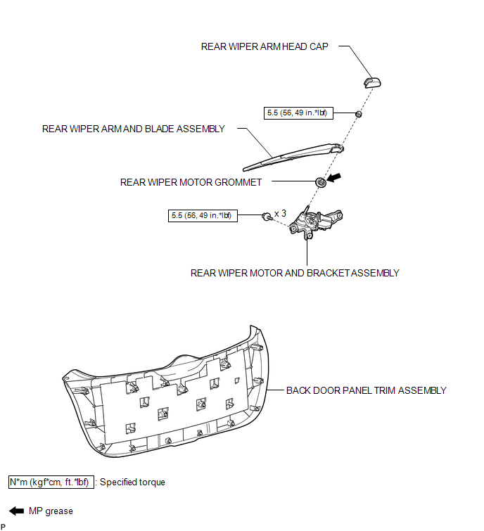
1. REMOVE BACK DOOR PANEL TRIM ASSEMBLY
.gif)
2. REMOVE REAR WIPER ARM HEAD CAP
3. REMOVE REAR WIPER ARM AND BLADE ASSEMBLY
4. REMOVE REAR WIPER MOTOR GROMMET
5. REMOVE REAR WIPER MOTOR AND BRACKET ASSEMBLY
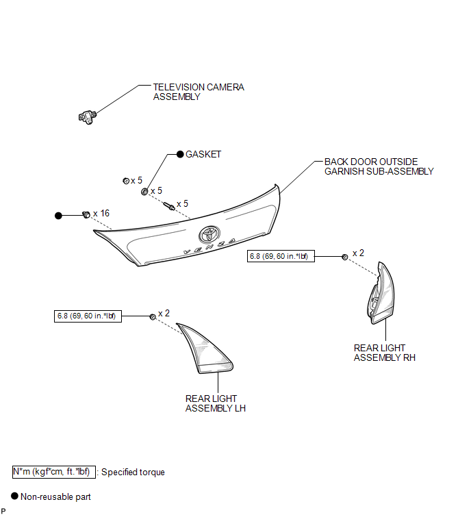
6. REMOVE REAR LIGHT ASSEMBLY LH
7. REMOVE REAR LIGHT ASSEMBLY RH
HINT:
Use the same procedure for the RH side and the LH side (See page
).
8. REMOVE BACK DOOR OUTSIDE GARNISH SUB-ASSEMBLY
9. REMOVE TELEVISION CAMERA ASSEMBLY
|
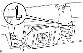
(a) Disengage the 2 claws and remove the television camera assembly. |
|
Installation
INSTALLATION
PROCEDURE
1. INSTALL TELEVISION CAMERA ASSEMBLY
|
(a) Engage the 2 claws to install the television camera assembly. |
|
.png)
2. INSTALL BACK DOOR OUTSIDE GARNISH SUB-ASSEMBLY
.gif)
3. INSTALL REAR LIGHT ASSEMBLY RH
HINT:
Use the same procedure for the RH side and the LH side (See page
).
4. INSTALL REAR LIGHT ASSEMBLY LH
5. INSTALL REAR WIPER MOTOR AND BRACKET ASSEMBLY
6. INSTALL REAR WIPER MOTOR GROMMET
7. INSTALL REAR WIPER ARM AND BLADE ASSEMBLY
8. INSTALL REAR WIPER ARM HEAD CAP
9. INSTALL BACK DOOR PANEL TRIM ASSEMBLY
 Image from Camera for Rear View Monitor is Abnormal
DESCRIPTION
The video signal of the rear television camera assembly is transmitted
to the navigation receiver assembly*1 or radio and display receiver assembly*2.
*1: for Navigation Sys ...
 Ultrasonic Sensor(for Front Side)
Components
COMPONENTS
ILLUSTRATION
Removal
REMOVAL
PROCEDURE
1. REMOVE FRONT BUMPER ASSEMBLY
(See page )
2. REMOVE NO. 1 ULTRASONIC SENSOR
(a) Disengage the 2 claws to remov ...
Other materials about Toyota Venza:
Adjustment
ADJUSTMENT
CAUTION / NOTICE / HINT
HINT:
Centering bolts are used to mount the hood hinge and hood lock. The
hood and hood lock cannot be adjusted with the centering bolts installed.
Substitute the centering bolts with standard bolts when ...
Terminals Of Ecm
TERMINALS OF ECM
1. CHECK ECM
Terminal No. (Symbol)
Wiring Color
Terminal Description
Condition
Specified Condition
A49-7 (TC) - B58-104 (E1)
V - BR
Terminal TC o ...
Registered Device cannot be Deleted
PROCEDURE
1.
DELETE OPERATION
(a) Check if a registered portable player can be deleted normally.
OK:
Registered portable player can be deleted normally.
OK
END
NG
PROCEED TO ...

0.1741