Toyota Venza: System Diagram
SYSTEM DIAGRAM
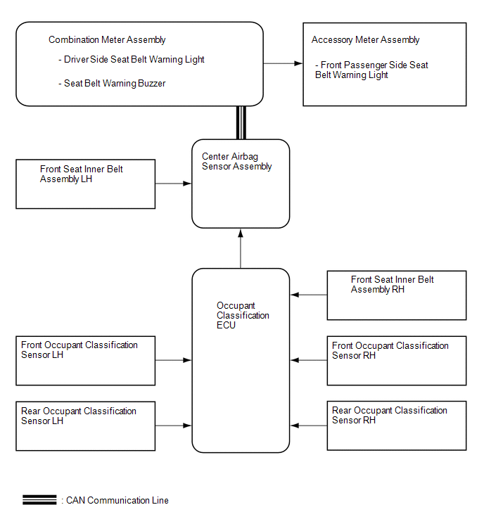 Communication Table
|
Sender |
Receiver |
Signal |
Communication Method |
|---|---|---|---|
|
Center airbag sensor assembly |
Combination meter assembly |
|
CAN |
 System Description
SYSTEM DESCRIPTION
1. SEAT BELT WARNING SYSTEM DESCRIPTION
If a seat belt is not fastened, this system flashes the seat belt warning light
or sounds the seat belt warning buzzer as a reminder.
(a ...
 How To Proceed With Troubleshooting
CAUTION / NOTICE / HINT
HINT:
Use these procedure to troubleshoot the seat belt warning system.
*: Use the Techstream.
PROCEDURE
1.
VEHICLE BROUGHT TO W ...
Other materials about Toyota Venza:
Inspection
INSPECTION
PROCEDURE
1. INSPECT ATF TEMPERATURE SENSOR ASSEMBLY
(a) Measure the resistance according to the value(s) in the table below.
Standard Resistance:
Tester Connection
Condition
Sp ...
Intake Air Temperature Circuit Low Input (P0112,P0113)
DESCRIPTION
The intake air temperature sensor, in the mass air flow meter, monitors
the intake air temperature. The intake air temperature sensor has a built-in
thermistor with a resistance that varies according to the temperature of
the ...
Inspection
INSPECTION
PROCEDURE
1. INSPECT FRONT LOWER BALL JOINT
(a) Inspect the turning torque of the ball joint.
(1) Secure the front lower ball joint in a vise using aluminum plates.
(2) Install the nut to the front lower ball joint stud.
(3) U ...

0.1125