Toyota Venza: Transfer Case Rear Oil Seal
Components
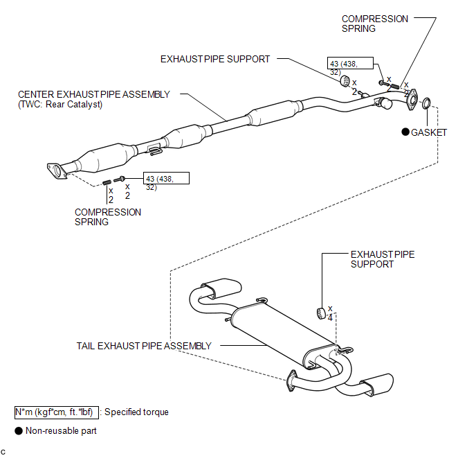
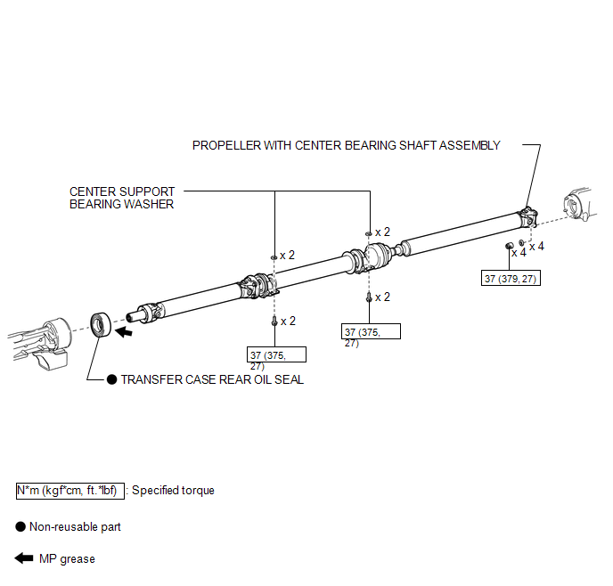
COMPONENTS
ILLUSTRATION
ILLUSTRATION
Replacement
REPLACEMENT
PROCEDURE
1. REMOVE TAIL EXHAUST PIPE ASSEMBLY
.gif)
2. REMOVE CENTER EXHAUST PIPE ASSEMBLY
3. REMOVE PROPELLER WITH CENTER BEARING SHAFT ASSEMBLY
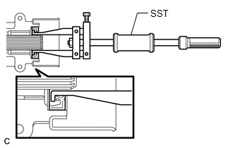
4. REMOVE TRANSFER CASE REAR OIL SEAL
|
(a) Using SST, remove the transfer case rear oil seal from the transfer extension housing sub-assembly. SST: 09308-00010 NOTICE: Be careful not to damage the oil seal contact surface or the inside surface of the oil seal. |
|
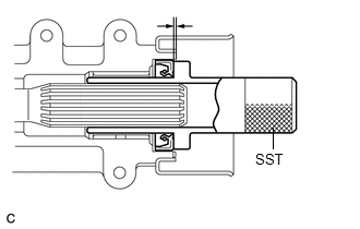
5. INSTALL TRANSFER CASE REAR OIL SEAL
|
(a) Using SST and a hammer, drive in a new transfer case rear oil seal into the transfer extension housing sub-assembly until it reaches the position shown in the illustration. SST: 09325-20010 Drive in depth: 1.1 to 1.9 mm (0.0433 to 0.0748 in.) NOTICE: Do not tilt the oil seal during installation. |
|
(b) Apply a small amount of MP grease to the lip of the oil seal.
6. TEMPORARILY TIGHTEN PROPELLER WITH CENTER BEARING SHAFT ASSEMBLY
7. FULLY TIGHTEN PROPELLER WITH CENTER BEARING SHAFT ASSEMBLY
8. INSTALL CENTER EXHAUST PIPE ASSEMBLY
9. INSTALL TAIL EXHAUST PIPE ASSEMBLY
10. INSPECT TRANSFER OIL
11. INSPECT EXHAUST GAS LEAK
 Transfer Case Front Oil Seal(for Rh Side)
Components
COMPONENTS
ILLUSTRATION
Replacement
REPLACEMENT
PROCEDURE
1. DRAIN TRANSFER OIL
(a) Remove the transfer drain plug and gasket to drain the transfer oil.
(b) Install a new gask ...
 Transfer Oil
On-vehicle Inspection
ON-VEHICLE INSPECTION
PROCEDURE
1. INSPECT TRANSFER OIL
(a) Remove the No. 1 transfer case plug and gasket.
...
Other materials about Toyota Venza:
TC and CG Terminal Circuit
DESCRIPTION
Connecting terminals TC and CG of the DLC3 causes the ECU to display the DTC
by blinking the ABS warning and slip indicator lights.
WIRING DIAGRAM
CAUTION / NOTICE / HINT
HINT:
When the warning lights continue to blink, a ground short in t ...
No Communication in Immobiliser System (B2796,B2798)
DESCRIPTION
These DTCs are stored if a key that does not have a transponder chip is inserted
into the ignition key cylinder or if communication between the key and the transponder
key ECU assembly is impossible.
DTC No.
DTC Detectio ...
Inspection
INSPECTION
PROCEDURE
1. INSPECT WINDSHIELD WIPER SWITCH ASSEMBLY
(a) Measure the resistance according to the value(s) in the table below.
Standard Resistance:
Front Wiper Switch
Tester Connection
Switch ...

0.1591