Toyota Venza: Transfer Oil
On-vehicle Inspection
ON-VEHICLE INSPECTION
PROCEDURE
1. INSPECT TRANSFER OIL
|
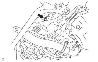
(a) Remove the No. 1 transfer case plug and gasket. |
|
|
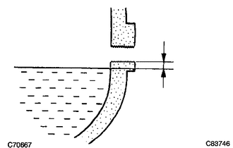
(b) Check that the oil level is between 0 and 5 mm (0 and 0.197 in.) from the bottom lip of the case plug hole. NOTICE:
|
|
(c) Check for oil leakage if the oil level is low.
(d) Install a new gasket onto the No. 1 transfer case plug and then tighten the plug.
Torque:
49 N·m {500 kgf·cm, 36 ft·lbf}
2. ADJUST TRANSFER OIL
(a) Remove the No. 1 transfer case plug and gasket.
(b) Add oil until the oil level is between 0 and 5 mm (0 and 0.197 in.) from the bottom lip of the case plug hole.
NOTICE:
- When adding transfer oil, make sure the vehicle is level.
- Add oil slowly, waiting several minutes between each addition.
- An excessively large or small amount of oil may cause damage.
- After adding oil, drive the vehicle and recheck the oil level.
HINT:
-
Oil grade:
API GL-5
Viscosity:
Above 0°F(-18°C): SAE 90
Below 0°F(-18°C): SAE 80W or 80W-90
Capacity:
0.8 liters (0.84 US qts, 0.70 lmp.qts)
(c) After waiting for approximately 5 minutes, recheck the oil level.
(d) Install a new gasket onto the No. 1 transfer case plug and then tighten the plug.
Torque:
49 N·m {500 kgf·cm, 36 ft·lbf}
 Transfer Case Rear Oil Seal
Components
COMPONENTS
ILLUSTRATION
ILLUSTRATION
Replacement
REPLACEMENT
PROCEDURE
1. REMOVE TAIL EXHAUST PIPE ASSEMBLY
2. REMOVE CENTER EXHAUST PIPE ASSEMBLY
3. REMOVE PROPELLER ...
 Transfer System
Precaution
PRECAUTION
Prior to starting any work, clean the transfer assembly to prevent sand
or mud deposits from entering the assembly.
When removing any light alloy components su ...
Other materials about Toyota Venza:
Removal
REMOVAL
PROCEDURE
1. REMOVE ROOF DRIP CENTER SIDE FINISH MOULDING (w/o Sliding Roof)
(a) Put protective tape around the roof drip center side finish moulding.
Text in Illustration
*1
Protective Tape
...
On-vehicle Inspection
ON-VEHICLE INSPECTION
PROCEDURE
1. INSPECT CAMSHAFT TIMING OIL CONTROL VALVE ASSEMBLY
(a) Connect the Techstream to the DLC3.
(b) Start the engine and turn the Techstream on.
(c) Inspect the oil control valve (for intake camshaft).
(1) Enter the followin ...
Removal
REMOVAL
PROCEDURE
1. REMOVE COOL AIR INTAKE DUCT SEAL
2. REMOVE INLET NO. 2 AIR CLEANER
3. REMOVE AIR CLEANER CAP WITH HOSE
4. REMOVE AIR CLEANER CASE
5. REMOVE AIR CLEANER BRACKET
(a) Separate the wire harness clamp.
...

0.16