Toyota Venza: Transfer Case Front Oil Seal(for Rh Side)
Components
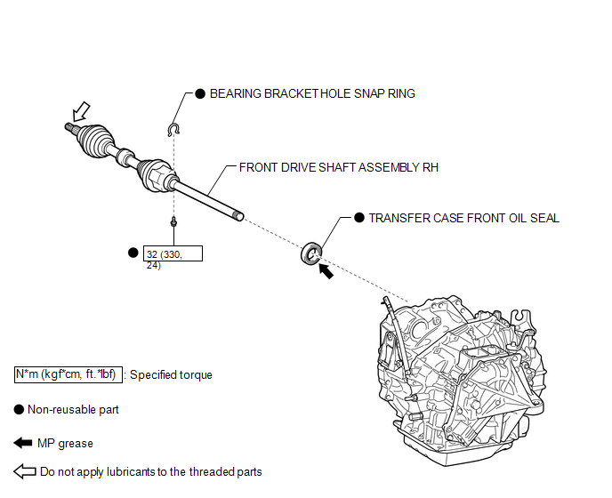
COMPONENTS
ILLUSTRATION
Replacement
REPLACEMENT
PROCEDURE
1. DRAIN TRANSFER OIL
(a) Remove the transfer drain plug and gasket to drain the transfer oil.
(b) Install a new gasket and the transfer drain plug.
Torque:
49 N·m {500 kgf·cm, 36 ft·lbf}
2. REMOVE FRONT DRIVE SHAFT ASSEMBLY RH
(See page .gif) ).
).
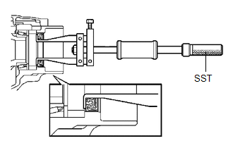
3. REMOVE TRANSFER CASE FRONT OIL SEAL
|
(a) Using SST, remove the transfer case front oil seal from the transfer case. SST: 09308-00010 NOTICE: Do not damage the oil seal contact surface on the case. |
|
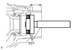
4. INSTALL TRANSFER CASE FRONT OIL SEAL
|
(a) Using SST, drive in a new transfer case front oil seal into the transfer case until it reaches the position shown in the illustration. SST: 09950-60010 09951-00350 09951-00580 09952-06010 SST: 09950-70010 09951-07150 Drive in depth: 33.5 to 34.5 mm (1.319 to 1.358 in.) NOTICE: Do not tilt the oil seal during installation. |
|
(b) Apply a small amount of MP grease to the lip of the oil seal.
5. INSTALL FRONT DRIVE SHAFT ASSEMBLY RH
(See page ).
6. ADD TRANSFER OIL
7. INSPECT TRANSFER OIL
 Transfer Case Front Oil Seal(when Using The Engine Support Bridge)
Components
COMPONENTS
ILLUSTRATION
Replacement
REPLACEMENT
PROCEDURE
1. REMOVE TRANSFER ASSEMBLY
See page
2. REMOVE TRANSFER CASE FRONT OIL SEAL
(a) Using SST, remove the t ...
 Transfer Case Rear Oil Seal
Components
COMPONENTS
ILLUSTRATION
ILLUSTRATION
Replacement
REPLACEMENT
PROCEDURE
1. REMOVE TAIL EXHAUST PIPE ASSEMBLY
2. REMOVE CENTER EXHAUST PIPE ASSEMBLY
3. REMOVE PROPELLER ...
Other materials about Toyota Venza:
Rear Wiper Rubber
Components
COMPONENTS
ILLUSTRATION
Replacement
REPLACEMENT
PROCEDURE
1. REMOVE REAR WIPER BLADE
(a) Disconnect the rear wiper arm head cap.
(b) Raise the wiper blade to the posi ...
Unmatched Key Code (B2795)
DESCRIPTION
This DTC is stored when a key with a key code that has not been registered in
the ECU is inserted into the ignition key cylinder.
DTC No.
DTC Detection Condition
Trouble Area
B2795
Ke ...
Diagnosis System
DIAGNOSIS SYSTEM
1. DESCRIPTION
(a) The power window control system data can be read from the Data Link Connector
3 (DLC3) of the vehicle. When the system seems to be malfunctioning, use the Techstream
to check for malfunctions and perform repairs.
2. C ...

0.1426