Toyota Venza: Tire Pressure Warning Receiver
Components
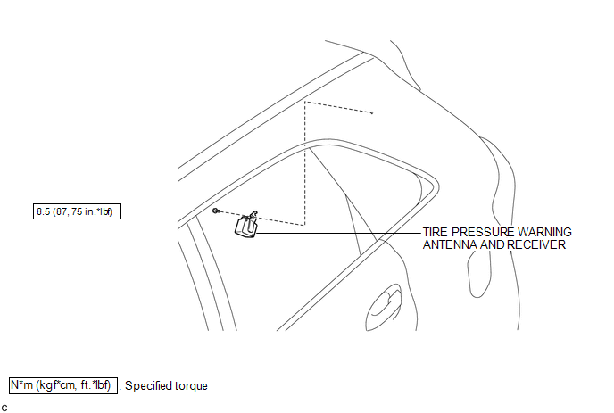
COMPONENTS
ILLUSTRATION
Removal
REMOVAL
PROCEDURE
1. DISCONNECT CABLE FROM NEGATIVE BATTERY TERMINAL
NOTICE:
When disconnecting the cable, some systems need to be initialized after the cable
is reconnected (See page .gif) ).
).
2. REMOVE ROOF SIDE INNER GARNISH ASSEMBLY LH
HINT:
- Refer to the procedures up to "Remove roof side inner garnish assembly"
(See page ).
- Removal should be performed only for the left side.
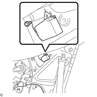
3. REMOVE TIRE PRESSURE WARNING ANTENNA AND RECEIVER
|
(a) Remove the bolt. |
|
|
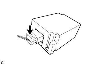
(b) Disconnect the connector to remove the tire pressure warning antenna and receiver. |
|
Installation
INSTALLATION
PROCEDURE
1. INSTALL TIRE PRESSURE WARNING ANTENNA AND RECEIVER
|
(a) Connect the connector. |
|
.png)
|
(b) Engage the 2 tabs into the holes as shown in the illustration to install the tire pressure warning antenna and receiver. |
|
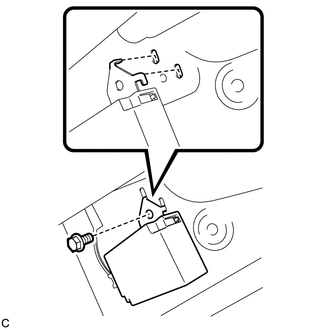
(c) Install the bolt.
Torque:
8.5 N·m {87 kgf·cm, 75 in·lbf}
2. INSTALL ROOF SIDE INNER GARNISH ASSEMBLY LH
HINT:
- Refer to the procedures from "Install roof side inner garnish assembly"
(See page
.gif) ).
). - Installation should be performed only for the left side.
3. CONNECT CABLE TO NEGATIVE BATTERY TERMINAL
NOTICE:
When disconnecting the cable, some systems need to be initialized after the cable
is reconnected (See page ).
4. INSPECT TIRE PRESSURE WARNING SYSTEM
(a) Inspect the tire pressure warning system (See page
).
 Tire Pressure Warning Ecu
Components
COMPONENTS
ILLUSTRATION
ILLUSTRATION
Removal
REMOVAL
CAUTION / NOTICE / HINT
NOTICE:
Before removing the tire pressure warning ECU, read the registered transmitter
IDs of ...

Other materials about Toyota Venza:
Dtc Check / Clear
DTC CHECK / CLEAR
HINT:
Use the Techstream to read and clear the DTC of the occupant classification ECU,
otherwise the DTCs cannot be read and cleared.
1. DTC CHECK
(a) Turn the ignition switch off.
(b) Connect the Techstream to the DLC3.
(c) Turn the ...
Removal
REMOVAL
PROCEDURE
1. DISCONNECT CABLE FROM NEGATIVE BATTERY TERMINAL
NOTICE:
When disconnecting the cable, some systems need to be initialized after the cable
is reconnected (See page ).
2. RECOVER REFRIGERANT FROM REFRIGERATION SYSTEM
3. REMOVE CO ...
Dtc Check / Clear
DTC CHECK / CLEAR
NOTICE:
When the diagnosis system is changed from normal mode to check mode or vice versa,
all DTCs and freeze frame data recorded in normal mode are cleared. Before changing
modes, always check and make a note of DTCs and freeze frame ...

0.1266