Toyota Venza: Installation
INSTALLATION
PROCEDURE
1. INSTALL REAR SEAT ASSEMBLY LH
(a) Place the rear seat assembly LH in the cabin.
NOTICE:
Be careful not to damage the vehicle body.
|
(b) Temporarily install the 2 bolts on the front side of the seat. |
|
.png)
|
(c) Temporarily install the 2 bolts on the rear side of the seat. |
|
.png)
(d) Install the rear seat assembly LH with the 4 bolts.
Torque:
37 N·m {377 kgf·cm, 27 ft·lbf}
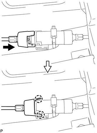
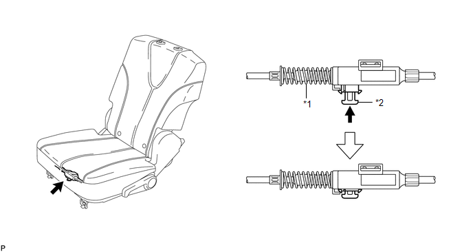
2. CONNECT REAR SEAT NO. 2 RECLINING CONTROL CABLE SUB-ASSEMBLY
(a) Remove the rear seat No. 2 reclining control cable from the carpet hole.
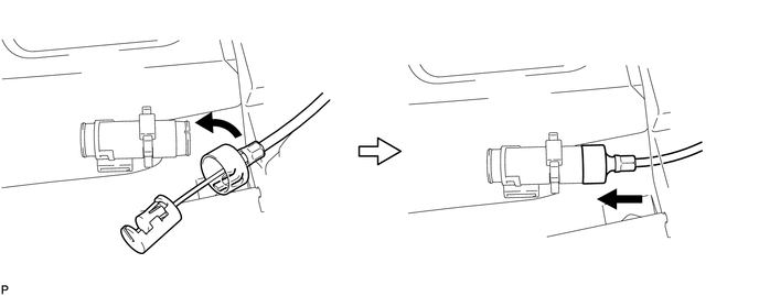
(b) Connect the rear seat No. 2 reclining control cable sub-assembly as shown in the illustration.
 Text in Illustration
|
*1 |
Protective Tape |
*2 |
Seat Track Adjusting Handle |
|
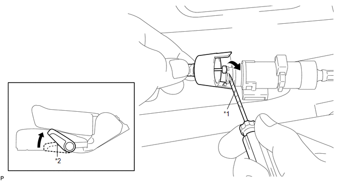
(c) Engage the 2 claws and connect the rear seat No. 2 reclining control cable sub-assembly as shown in the illustration. |
|
(d) Return the seatback to the upright position.
(e) Pull up the adjuster's lock piece to lock it as shown in the illustration.
 Text in Illustration
|
*1 |
Adjuster Spring |
*2 |
Lock Piece |
NOTICE:
When pressing the lock piece, make sure the adjuster's spring is not compressed.
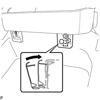
3. INSTALL REAR SEAT OUTER TRACK BRACKET COVER
|
(a) Engage the guide and 3 claws and install the rear seat outer track bracket cover as shown in the illustration. |
|
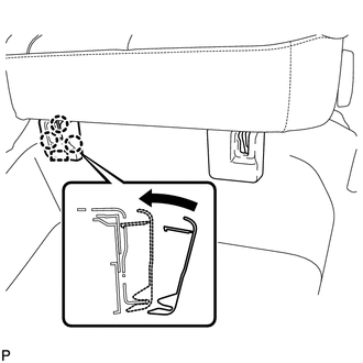
4. INSTALL REAR SEAT INNER TRACK BRACKET COVER
|
(a) Engage the guide and 3 claws and install the rear seat inner track bracket cover as shown in the illustration. |
|
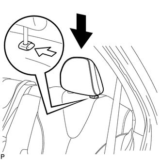
5. INSTALL REAR SEAT HEADREST ASSEMBLY
|
(a) Install the rear seat headrest assembly as shown in the illustration. |
|
 Disassembly
DISASSEMBLY
PROCEDURE
1. REMOVE SEAT ADJUSTER COVER CAP LH
(a) Using a screwdriver wrapped with protective tape, disengage the 3
claws and remove the seat adjuster cover cap LH.
T ...

Other materials about Toyota Venza:
Installation
INSTALLATION
PROCEDURE
1. INSTALL VACUUM SWITCHING VALVE ASSEMBLY (for ACIS)
(a) Install the vacuum switching valve assembly (for ACIS) with the bolt.
Torque:
9.0 N·m {92 kgf·cm, 80 in·lbf}
...
Oxygen (A/F) Sensor Pumping Current Circuit / Open (Bank 1 Sensor 1) (P2237-P2239,P2252,P2253)
DESCRIPTION
Refer to DTC P2195 (See page ).
HINT:
Although the DTC titles say oxygen sensor, these DTCs relate to the air fuel
ratio sensor.
DTC No.
DTC Detection Condition
Trouble Area
P2237
...
Compass
The compass on the inside rear view mirror indicates the direction in which
the vehicle is heading.
- Operation
To turn the compass on or off, push and hold “AUTO” for longer than 3 seconds.
- Displays and directions
Calibrating the c ...

0.1266