Toyota Venza: Washer Nozzle(for Rear Side)
Components
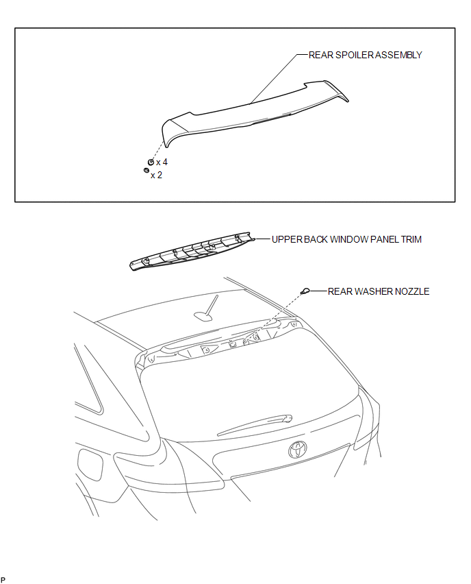
COMPONENTS
ILLUSTRATION
On-vehicle Inspection
ON-VEHICLE INSPECTION
PROCEDURE
1. INSPECT REAR WASHER NOZZLE
(a) With the engine running, check where the washer fluid hits the windshield.
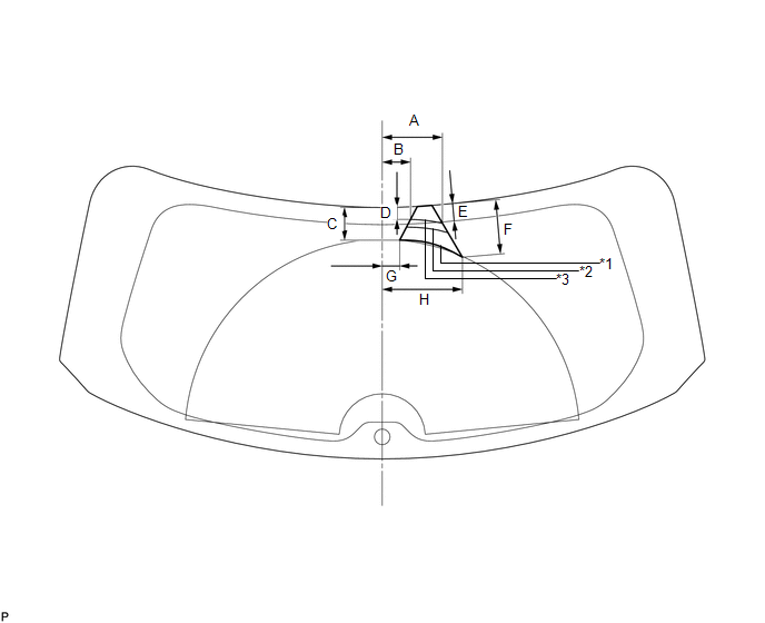 Standard Measurement
|
Area |
Dimension |
Area |
Dimension |
|---|---|---|---|
|
A |
134.4 mm (5.29 in.) |
B |
63.5 mm (2.50 in.) |
|
C |
75.4 mm (2.97 in.) |
D |
28.2 mm (1.11 in.) |
|
E |
38.1 mm (1.50 in.) |
F |
120 mm (4.72 in.) |
|
G |
38.7 mm (1.52 in.) |
H |
180.1 mm (7.09 in.) |
|
*1 |
Minimum Spray |
*2 |
Maximum Spray |
|
*3 |
Nominal Spray |
- |
- |
OK:
Washer fluid hits the windshield in the area shown in the illustration.
Adjustment
ADJUSTMENT
PROCEDURE
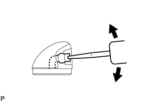
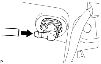
1. ADJUST REAR WASHER NOZZLE
|
(a) Using a screwdriver, adjust the direction of the rear washer nozzle. NOTICE: Do not use a safety pin or other pointed tools. Doing so may damage the inside of the washer nozzle. HINT: Use a thin-bladed screwdriver with an approximately 1 mm (0.0394 in.) thick tip. |
|
Removal
REMOVAL
PROCEDURE
1. REMOVE UPPER BACK WINDOW PANEL TRIM
.gif)
2. REMOVE REAR SPOILER ASSEMBLY
3. REMOVE REAR WASHER NOZZLE
|
(a) Disconnect the washer hose. |
|
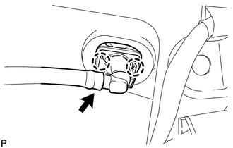
(b) Disengage the 2 claws and remove the rear washer nozzle.
Installation
INSTALLATION
PROCEDURE
1. INSTALL REAR WASHER NOZZLE
|
(a) Engage the 2 claws to install the rear washer nozzle. |
|
(b) Connect the washer hose.
2. INSPECT REAR WASHER NOZZLE
.gif)
3. ADJUST REAR WASHER NOZZLE
4. INSTALL REAR SPOILER ASSEMBLY
5. INSTALL UPPER BACK WINDOW PANEL TRIM
 Washer Nozzle(for Front Side)
Components
COMPONENTS
ILLUSTRATION
On-vehicle Inspection
ON-VEHICLE INSPECTION
PROCEDURE
1. INSPECT FRONT WASHER NOZZLE SUB-ASSEMBLY
(a) With the engine running, check that the center str ...

Other materials about Toyota Venza:
Components
COMPONENTS
ILLUSTRATION
ILLUSTRATION
ILLUSTRATION
ILLUSTRATION
ILLUSTRATION
ILLUSTRATION
ILLUSTRATION
ILLUSTRATION
...
Installation
INSTALLATION
PROCEDURE
1. INSTALL REAR SEAT INNER BELT ASSEMBLY LH
(a) Install the rear seat inner belt assembly LH with the bolt.
Text in Illustration
*1
Protruding Part
Torque:
42 N┬ ...
Installation
INSTALLATION
CAUTION / NOTICE / HINT
NOTICE:
When disconnecting the steering intermediate shaft assembly and pinion shaft
of steering gear assembly, be sure to place matchmarks before servicing.
PROCEDURE
1. INSTALL TIE ROD ASSEMBLY LH
(a) I ...

0.1202