Toyota Venza: Test Mode Procedure
TEST MODE PROCEDURE
1. DESCRIPTION
HINT:
When using a chassis dynamometer, brake tester, etc. to perform a vehicle test, activate test mode to avoid a "different tire diameter installed" incorrect judgment.
Test mode does not have a AWD parameter. Test mode is activated because it will prohibit a different tire diameter judgment.
|
Control Status |
AWD Control Status |
|---|---|
|
During test mode |
Different tire diameter malfunction judgement (detection that tire diameter of all wheels are not same) is not performed. |
2. ACTIVATE TEST MODE
HINT:
Activate test mode before using a chassis dynamometer, brake tester, etc. to perform a vehicle test.
(a) Check that the ignition switch is off.
(b) Use either of the following methods to change the AWD control ECU to test mode.
(1) Test mode activation through the Techstream
- Connect the Techstream to the DLC3 connector and turn the ignition switch to ON. Using the test mode activation function (mode 10), activate test mode.
(2) Test mode activation by shorting the TS terminal
- With the ignition switch off, connect the TS and CG terminals of the
DLC3 connector. Then turn the ignition switch to ON to activate test mode.
NOTICE:
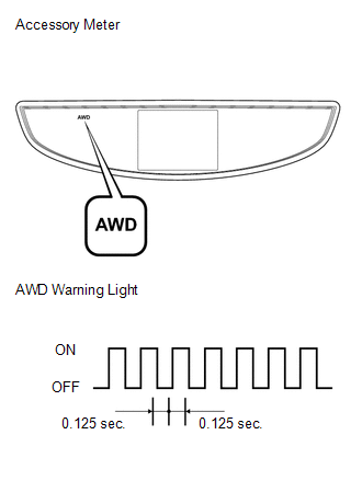
When the ignition switch is turned from off to ON, the AWD warning light will illuminate for 4 seconds. Then it will turn off.
NOTICE:
If a part of the active torque control 4WD system has a defect, the AWD warning light will illuminate.
(c) Check if the AWD warning light has changed to the test mode display.
(d) Start the engine.
 Problem Symptoms Table
PROBLEM SYMPTOMS TABLE
HINT:
Use the table below to help determine the cause of problem symptoms.
If multiple suspected areas are listed, the potential causes of the symptoms
are lis ...
 Terminals Of Ecu
TERMINALS OF ECU
1. CHECK AWD CONTROL ECU
(a) Measure the voltage and resistance of the connector.
Terminal No. (Symbol)
Terminal Description
Condition
...
Other materials about Toyota Venza:
Initialization has not been Performed (B2450)
DESCRIPTION
The headlight leveling ECU assembly stores this DTC if initialization has not
been performed after the ECU was replaced.
DTC No.
DTC Detecting Condition
Trouble Area
B2450
Initializat ...
System Diagram
SYSTEM DIAGRAM
Communication Table
Sender
Receiver
Signal
Line
ECM
Main Body ECU (Driver Side Junction Block Assembly)
Transmission information
Park (P) st ...
If you have a flat tire
Remove the flat tire and replace it with the spare provided. - Before
jacking up the vehicle
• Stop the vehicle on a hard, flat surface.
• Set the parking brake.
• Shift the shift lever to “P”.
• Stop the engine.
• Turn on the emergency f ...

0.1286