Toyota Venza: Terminals Of Ecu
TERMINALS OF ECU
1. CHECK AWD CONTROL ECU
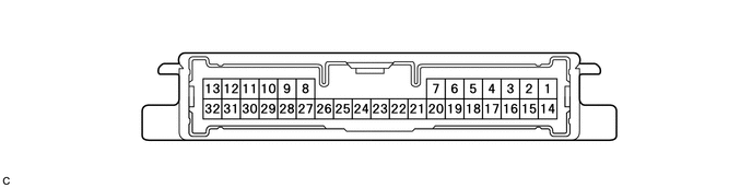
(a) Measure the voltage and resistance of the connector.
|
Terminal No. (Symbol) |
Terminal Description |
Condition |
Specified Condition |
|---|---|---|---|
|
14 (CANH) - 16 (CANL) |
CAN communication |
Ignition switch off |
54 to 69 Ω |
|
23 (GND) - Body ground |
Ground |
Always |
Below 1 Ω |
|
11 (IG1) - 23 (GND) |
Power source voltage |
Ignition switch ON |
10 to 14 V |
|
13 (SLC+) - 32 (SLC-) |
Electromagnetic solenoid signal |
D position, Idling |
Pulse generation (See waveform 1) |
|
9 (BSLC) - 23 (GND) |
Power source voltage |
Always |
10 to 14 V |
If the result is not as specified, the AWD control ECU may have a malfunction.
(b) Using an oscilloscope, check the waveform 1.
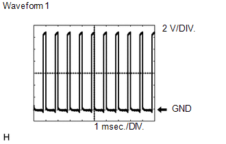 Waveform 1 (Reference)
|
Terminal Name |
Content |
|---|---|
|
Tester Range |
2 V/DIV., 1 msec./DIV. |
|
Condition |
D position, Idling |
 Test Mode Procedure
TEST MODE PROCEDURE
1. DESCRIPTION
HINT:
When using a chassis dynamometer, brake tester, etc. to perform a vehicle test,
activate test mode to avoid a "different tire diameter installed" ...
 Diagnosis System
DIAGNOSIS SYSTEM
1. DESCRIPTION
Active torque control 4WD system data can be read in the Data Link Connector
3 (DLC3) of the vehicle. When the system seems to be malfunctioning, use the Techstream ...
Other materials about Toyota Venza:
Inspection
INSPECTION
PROCEDURE
1. INSPECT REAR SPEAKER ASSEMBLY
(a) With the speaker installed, check that there is no looseness or other abnormalities.
(b) Check that there is no foreign matter in the speaker, no tears on the speaker
cone or other abnormalities.
...
Certification ECU Communication Stop Mode
DESCRIPTION
Detection Item
Symptom
Trouble Area
Certification ECU Communication Stop Mode
"Smart Access/Smart Key/Wireless Tuner" is not displayed on
"CAN Bus Check&q ...
On-vehicle Inspection
ON-VEHICLE INSPECTION
CAUTION / NOTICE / HINT
CAUTION:
Be sure to follow the correct removal and installation procedures of the rear
airbag sensor.
PROCEDURE
1. INSPECT REAR AIRBAG SENSOR (VEHICLE NOT INVOLVED IN COLLISION)
(a) Perform a diagnostic sys ...

0.1688