Toyota Venza: Tcm
Components
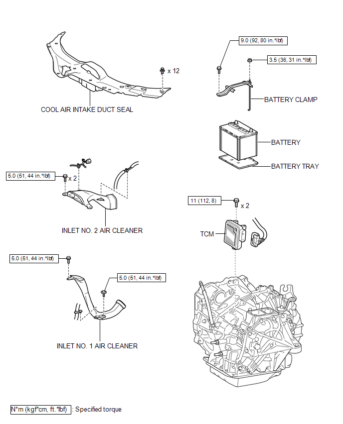
COMPONENTS
ILLUSTRATION
Removal
REMOVAL
CAUTION / NOTICE / HINT
NOTICE:
If automatic transmission parts are replaced, refer to Parts Replacement Compensation
Table to determine if any additional operations are necessary (See page
.gif) ).
).
PROCEDURE
1. DISCONNECT CABLE FROM NEGATIVE BATTERY TERMINAL
NOTICE:
When disconnecting the cable, some systems need to be initialized after the cable
is reconnected (See page ).
2. REMOVE COOL AIR INTAKE DUCT SEAL
3. REMOVE INLET NO. 2 AIR CLEANER
4. REMOVE BATTERY
5. REMOVE INLET NO. 1 AIR CLEANER
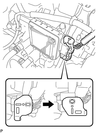
6. REMOVE TCM
|
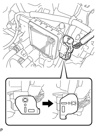
(a) Turn the lock lever and disconnect the connector from the TCM. |
|
|
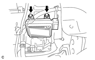
(b) Remove the 2 bolts and TCM from the transaxle. |
|
Installation
INSTALLATION
PROCEDURE
1. INSTALL TCM
(a) Install the TCM to the transaxle.
|
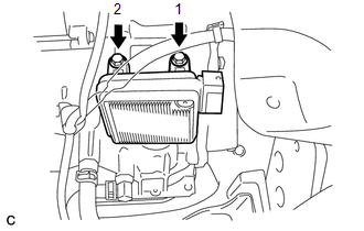
(b) Install and tighten the 2 bolts in the order shown in the illustration. Torque: 11 N·m {112 kgf·cm, 8 ft·lbf} |
|
|
(c) Connect the connector to the TCM. |
|
(d) Turn the lock lever and secure the connector with the lock lever.
2. INSTALL INLET NO. 1 AIR CLEANER
.gif)
3. INSTALL BATTERY
4. INSTALL INLET NO. 2 AIR CLEANER
5. INSTALL COOL AIR INTAKE DUCT SEAL
6. CONNECT CABLE TO NEGATIVE BATTERY TERMINAL
NOTICE:
When disconnecting the cable, some systems need to be initialized after the cable
is reconnected (See page ).
7. CHECK AUTOMATIC TRANSAXLE SYSTEM
NOTICE:
If automatic transmission parts have been replaced, refer to Parts Replacement
Compensation Table to determine if any additional operations are necessary (See
page ).
 Speed Sensor(when Using The Engine Support Bridge)
Components
COMPONENTS
ILLUSTRATION
Removal
REMOVAL
PROCEDURE
1. REMOVE TRANSMISSION VALVE BODY ASSEMBLY
See page
2. REMOVE SPEED SENSOR
(a) Disconnect the speed sensor connector.
...
 Torque Converter And Drive Plate
Inspection
INSPECTION
PROCEDURE
1. INSPECT TORQUE CONVERTER ASSEMBLY
(a) Inspect the one-way clutch.
(1) Press on the serrations of the stator with a finger and rotate it.
Check ...
Other materials about Toyota Venza:
On-vehicle Inspection
ON-VEHICLE INSPECTION
PROCEDURE
1. INSPECT SPEEDOMETER
(a) Check the operation.
(1) Using a speedometer tester (calibrated chassis dynamometer), check the speedometer
indication according to the table below.
Reference:
Chassis Dynamometer In ...
Inspection
INSPECTION
PROCEDURE
1. INSPECT SHIFT LOCK CONTROL UNIT ASSEMBLY (w/o Smart Key System)
(a) Measure the voltage according to the value(s) in the table below.
Text in Illustration
*1
Component with harness c ...
IG Signal Circuit
DESCRIPTION
This circuit detects the ignition switch ON or off condition, and sends it to
the main body ECU (driver side junction block assembly).
WIRING DIAGRAM
CAUTION / NOTICE / HINT
NOTICE:
Inspect the fuses for circuits related to this system b ...

0.1158