Toyota Venza: Terminals Of Ecu
TERMINALS OF ECU
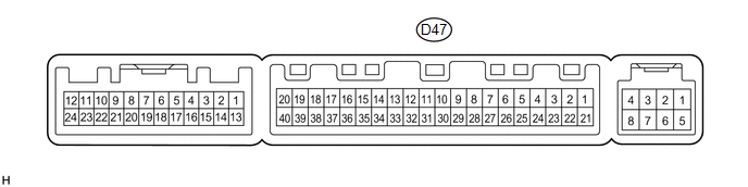
1. CHECK AIR CONDITIONING AMPLIFIER ASSEMBLY
(a) Disconnect the D47 air conditioning amplifier assembly connector.
(b) Measure the voltage and resistance according to the value(s) in the table below.
HINT:
Measure the values on the wire harness side with the connector disconnected.
|
Tester Connection |
Wiring Color |
Terminal Description |
Condition |
Specified Condition |
|---|---|---|---|---|
|
D47-1 (IG+) - D47-14 (GND) |
Y - W |
Power source (IG) |
Ignition switch ON |
11 to 14 V |
|
D47-1 (IG+) - D47-14 (GND) |
Y - W |
Power source (IG) |
Ignition switch off |
Below 1 V |
|
D47-21 (B) - D47-14 (GND) |
V - W |
Power source (Back-up) |
Always |
11 to 14 V |
|
D47-14 (GND) - Body ground |
W - Body ground |
Ground |
Always |
Below 1 Ω |
If the result is not as specified, there may be a malfunction in the wire harness.
(c) Reconnect the D47 air conditioning amplifier assembly connector.
(d) Measure the voltage and check for pulses according to the value(s) in the table below.
|
Tester Connection |
Wiring Color |
Terminal Description |
Condition |
Specified Condition |
|---|---|---|---|---|
|
D47-18 (D) - D47-14 (GND) |
G - W |
Rear defogger signal |
Ignition switch ON, rear window defogger switch off |
11 to 14 V |
|
D47-18 (D) - D47-14 (GND) |
G - W |
Rear defogger signal |
Ignition switch ON, rear window defogger switch on |
Below 1 V |
|
D47-37 (LIN1) - D47-14 (GND) |
SB - W |
LIN communication line |
Ignition switch ON |
Pulse generation |
If the result is not as specified, the air conditioning amplifier assembly may have a malfunction.
2. CHECK AIR CONDITIONING CONTROL ASSEMBLY
(a) Disconnect the E3 air conditioning control assembly connector.

(b) Measure the voltage and resistance according to the value(s) in the table below.
HINT:
Measure the values on the wire harness side with the connector disconnected.
|
Tester Connection |
Wiring Color |
Terminal Description |
Condition |
Specified Condition |
|---|---|---|---|---|
|
E3-4 (IG+) - E3-5 (GND) |
GR - W |
Power source (IG) |
Ignition switch ON |
11 to 14 V |
|
E3-4 (IG+) - E3-5 (GND) |
GR - W |
Power source (IG) |
Ignition switch off |
Below 1 V |
|
E3-5 (GND) - Body ground |
W - Body ground |
Ground |
Always |
Below 1 Ω |
If the result is not as specified, there may be a malfunction in the wire harness.
(c) Reconnect the E3 air conditioning control assembly connector.
(d) Check for pulses according to the value(s) in the table below.
|
Tester Connection |
Wiring Color |
Terminal Description |
Condition |
Specified Condition |
|---|---|---|---|---|
|
E3-2 (LIN1) - E3-5 (GND) |
SB - W |
LIN communication line |
Ignition switch ON |
Pulse generation |
If the result is not as specified, the air conditioning control assembly may have a malfunction.
 Problem Symptoms Table
PROBLEM SYMPTOMS TABLE
HINT:
Use the table below to help determine the cause of problem symptoms.
If multiple suspected areas are listed, the potential causes of the symptoms
are lis ...
 Data List / Active Test
DATA LIST / ACTIVE TEST
1. ACTIVE TEST
HINT:
Using the Techstream to perform Active Tests allows relays, VSVs, actuators and
other items to be operated without removing any parts. This non-intrus ...
Other materials about Toyota Venza:
Cold Start Ignition Timing Performance (P050B)
DESCRIPTION
This monitor will run when the engine is started at an engine coolant temperature
of -10 to 50°C (14 to 122°F). The DTC is stored after the engine idles for 13
seconds (2 trip detection logic).
The DTC is designed to monitor the ignition ti ...
Replacement
REPLACEMENT
CAUTION / NOTICE / HINT
CAUTION:
Prolonged and repeated contact with engine oil will result in the removal
of natural oils from the skin, leading to dryness, irritation and dermatitis.
In addition, used engine oil contains potent ...
Speaker Circuit
DESCRIPTION
If there is a short in a speaker circuit, the radio and display receiver
assembly detects it and stops output to the speakers.
Thus sound cannot be heard from the speakers even if there is no malfunction
in the radio and display ...

0.1452