Toyota Venza: Speed Sensor(when Using The Engine Support Bridge)
Components
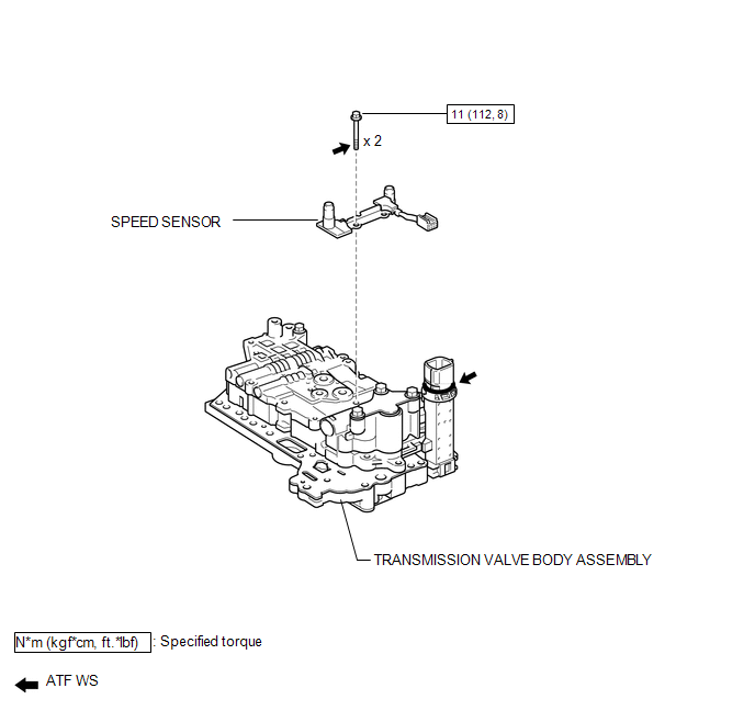
COMPONENTS
ILLUSTRATION
Removal
REMOVAL
PROCEDURE
1. REMOVE TRANSMISSION VALVE BODY ASSEMBLY
See page .gif)
2. REMOVE SPEED SENSOR
(a) Disconnect the speed sensor connector.
|
(b) Remove the 2 bolts and speed sensor from the transmission valve body assembly. |
|
.png)
Installation
INSTALLATION
PROCEDURE
1. INSTALL SPEED SENSOR
|
(a) Coat the 2 bolts with ATF. |
|
.png)
(b) Install the speed sensor to the transmission valve body assembly with the 2 bolts.
Torque:
11 N·m {112 kgf·cm, 8 ft·lbf}
(c) Connect the speed sensor connector.
2. INSTALL TRANSMISSION VALVE BODY ASSEMBLY
See page .gif)
 Speed Sensor(when Not Using The Engine Support Bridge)
Components
COMPONENTS
ILLUSTRATION
Removal
REMOVAL
PROCEDURE
1. REMOVE AUTOMATIC TRANSAXLE ASSEMBLY
HINT:
See the steps from "Remove Engine Assembly with transaxle" through &qu ...
 Tcm
Tcm
Components
COMPONENTS
ILLUSTRATION
Removal
REMOVAL
CAUTION / NOTICE / HINT
NOTICE:
If automatic transmission parts are replaced, refer to Parts Replacement Compensation
Table to determi ...
Other materials about Toyota Venza:
ECM Communication Stop Mode
DESCRIPTION
Detection Item
Symptom
Trouble Area
ECM Communication Stop Mode
"Engine" and "ECT" are not displayed on "CAN Bus Check" screen
of the Techs ...
Seat Heater Control
Components
COMPONENTS
ILLUSTRATION
Installation
INSTALLATION
PROCEDURE
1. INSTALL SEAT HEATER CONTROL SUB-ASSEMBLY
(a) Engage the clamp and install the seat heater control sub-assembly.
(b ...
Installation
INSTALLATION
PROCEDURE
1. INSTALL SPIRAL WITH SENSOR CABLE SUB-ASSEMBLY
(a) Install the spiral with sensor cable sub-assembly (See page
).
NOTICE:
Do not replace the spiral cable with the battery connected and the engine
switch on (IG).
...

0.1402