Toyota Venza: Torque Converter And Drive Plate
Inspection
INSPECTION
PROCEDURE
1. INSPECT TORQUE CONVERTER ASSEMBLY
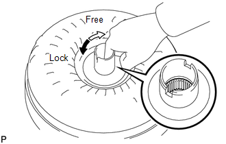
(a) Inspect the one-way clutch.
|
(1) Press on the serrations of the stator with a finger and rotate it. Check that it rotates smoothly when turned clockwise and locks when turned counterclockwise. If necessary, clean the converter and recheck the one-way clutch. Replace the converter if the one-way clutch still fails the check. |
|
|
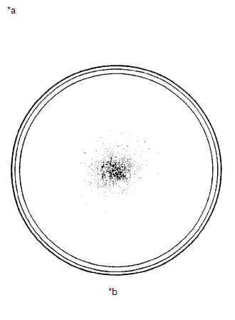
(b) Determine the condition of the torque converter assembly. Text in Illustration
(1) Check that the following conditions are met:
If the results are not as specified, replace the torque converter assembly. HINT: The sample illustration shows approximately 0.25 liters (0.26 US qts, 0.22 Imp. qts) of ATF taken from a removed torque converter. |
|
(c) Replace the ATF in the torque converter.
(1) If the ATF is discolored and/or has foul odor, stir the ATF in the torque converter thoroughly and drain it.
|
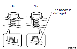
(d) Avoid damaging the torque converter and the oil pump gear. (1) When any marks due to interference are found on the end of a bolt for the torque converter or on the bottom of a bolt hole, replace the bolt and torque converter. (2) All of the bolts should be the same length. (3) Make sure that no spring washers are missing. |
|
2. INSPECT DRIVE PLATE
|
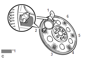
(a) Set up a dial indicator and measure the runout of the 6 portions around the torque converter contact surfaces. Text in Illustration
Maximum runout: 0.30 mm (0.0118 in.) |
|
(b) Check the drive plate damage.
If the runout is not within the specification or the drive plate is damaged, replace the drive plate.
 Tcm
Tcm
Components
COMPONENTS
ILLUSTRATION
Removal
REMOVAL
CAUTION / NOTICE / HINT
NOTICE:
If automatic transmission parts are replaced, refer to Parts Replacement Compensation
Table to determi ...

Other materials about Toyota Venza:
Problem Symptoms Table
PROBLEM SYMPTOMS TABLE
Use the table below to help determine the cause of problem symptoms.
If multiple suspected areas are listed, the potential causes of the symptoms
are listed in order of probability in the "Suspected Area" column ...
Precaution
PRECAUTION
NOTICE:
When disconnecting the cable from the negative (-) battery terminal, initialize
the following systems after the cable is reconnected.
System Name
See Procedure
Back Door Closer System
...
Installation
INSTALLATION
CAUTION / NOTICE / HINT
HINT:
Use the same procedure for the LH side and RH side.
The following procedure is for the LH side.
If the sensor rotor needs to be replaced, replace it together with the
front drive shaft assembly. ...

0.1157