Toyota Venza: TC and CG Terminal Circuit
DESCRIPTION
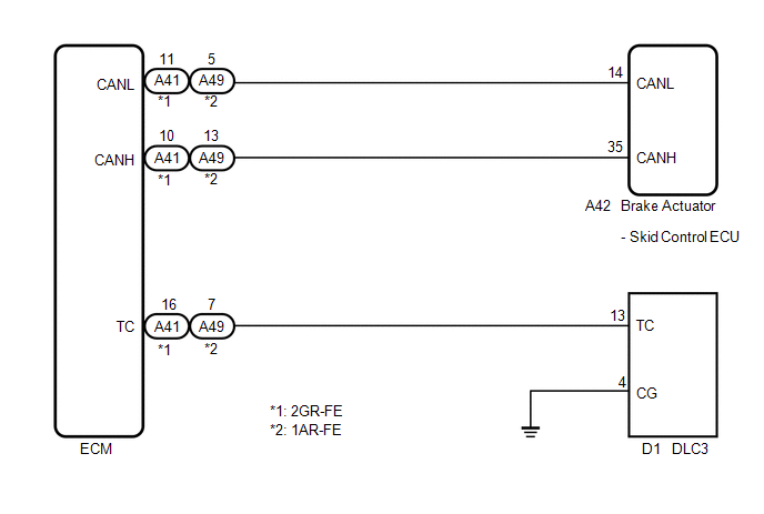
Connecting terminals TC and CG of the DLC3 causes the ECU to display the DTC by blinking the ABS warning and slip indicator lights.
WIRING DIAGRAM
CAUTION / NOTICE / HINT
HINT:
When the warning lights continue to blink, a ground short in the wiring of terminal TC of the DLC3 or an internal ground short in one or more ECUs is suspected.
PROCEDURE
|
1. |
CHECK CAN COMMUNICATION SYSTEM |
(a) Check if a CAN communication system DTC is output (See page
.gif) ).
).
|
Result |
Proceed to |
|---|---|
|
DTC is not output |
A |
|
DTC is output |
B |
| B | .gif) |
INSPECT CAN COMMUNICATION SYSTEM |
|
.gif)
|
2. |
INSPECT DLC3 |
|
(a) Turn the ignition switch to ON. |
|
(b) Measure the voltage according to the value(s) in the table below.
Standard Voltage:
|
Tester Connection |
Switch Condition |
Specified Condition |
|---|---|---|
|
D1-13 (TC) - D1-4 (CG) |
Ignition switch ON |
11 to 14 V |
|
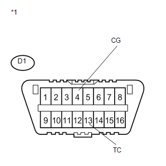
*1 |
Front view of DLC3 |
| NG | |
GO TO STEP 4 |
|
|
3. |
CHECK ECM (TC of DLC3 INPUT) |
|
(a) Turn the ignition switch off. |
|
(b) Reconnect the ECM connector.
(c) Using SST, connect terminals TC and CG of the DLC3.
SST: 09843-18040
Text in Illustration|
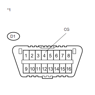
*1 |
Front view of DLC3 |
(d) Turn the ignition switch to ON.
(e) Check that the check engine warning light is blinking.
|
Result |
Proceed to |
|---|---|
|
Check engine warning light is blinking |
A |
|
Check engine warning light is not blinking |
B |
HINT:
If troubleshooting has been carried out according to Problem Symptoms Table,
refer back to the table and proceed to the next step before replacing the part (See
page ).
| A | |
REPLACE BRAKE ACTUATOR ASSEMBLY |
| B | |
REPAIR OR REPLACE WIRE HARNESS OR ECM (TC of ECM CIRCUIT) |
|
4. |
CHECK HARNESS AND CONNECTOR (TC of DLC3 - ECM) |
|
(a) Turn the ignition switch off. |
|
(b) Disconnect the ECM connector.
(c) Measure the resistance according to the value(s) in the table below.
Standard Resistance:
for 2GR-FE|
Tester Connection |
Condition |
Specified Condition |
|---|---|---|
|
D1-13 (TC) - A41-16 (TC) |
Always |
Below 1 Ω |
|
D1-13 (TC) - Body ground |
Always |
10 kΩ or higher |
|
Tester Connection |
Condition |
Specified Condition |
|---|---|---|
|
D1-13 (TC) - A49-7 (TC) |
Always |
Below 1 Ω |
|
D1-13 (TC) - Body ground |
Always |
10 kΩ or higher |
|
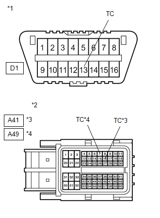
*1 |
Front view of DLC3 |
|
*2 |
Front view of wire harness connector (to ECM) |
|
*3 |
for 2GR-FE |
|
*4 |
for 1AR-FE |
| NG | |
REPAIR OR REPLACE HARNESS OR CONNECTOR |
|
|
5. |
CHECK HARNESS AND CONNECTOR (CG of DLC3 - BODY GROUND) |
|
(a) Measure the resistance according to the value(s) in the table below. Standard Resistance:
|
|
| NG | |
REPAIR OR REPLACE HARNESS OR CONNECTOR |
|
|
6. |
CHECK ECM (TC of DLC3 INPUT) |
|
(a) Turn the ignition switch off. |
|
(b) Reconnect the ECM connector.
(c) Using SST, connect terminals TC and CG of the DLC3.
SST: 09843-18040
Text in Illustration|
*1 |
Front view of DLC3 |
(d) Turn the ignition switch to ON.
(e) Check that the check engine warning light is blinking.
|
Result |
Proceed to |
|---|---|
|
Check engine warning light is blinking |
A |
|
Check engine warning light is not blinking |
B |
HINT:
If troubleshooting has been carried out according to Problem Symptoms Table,
refer back to the table and proceed to the next step before replacing the part (See
page ).
| A | |
REPLACE BRAKE ACTUATOR ASSEMBLY |
| B | |
REPAIR OR REPLACE WIRE HARNESS OR ECM (TC of ECM CIRCUIT) |
 Slip Indicator Light Remains ON
DESCRIPTION
The skid control ECU is connected to the combination meter via CAN communication.
The slip indicator light blinks during VSC and/or TRAC operation.
When the system fails, the slip indic ...
 TS and CG Terminal Circuit
DESCRIPTION
In the Test Mode (signal check), a malfunction in the speed sensor that cannot
be detected when the vehicle is stopped can be detected while driving.
Transition to the sensor check mod ...
Other materials about Toyota Venza:
Inspection
INSPECTION
PROCEDURE
1. INSPECT FUEL INJECTOR ASSEMBLY
(a) Measure the resistance according to the value(s) in the table below.
Standard Resistance:
Tester Connection
Condition
Specified C ...
Traffic Information is not Displayed
PROCEDURE
1.
CHECK DISPLAY
(a) Check which communication is not being used for displaying traffic information.
HINT:
Display of traffic information received via HD traffic is given priority while
in an "HD Radio" ...
Internal Control Module A/D Processing Performance (P060B)
MONITOR DESCRIPTION
This DTC is stored when a communication error occurs in the ECM.
DTC Code
DTC Detection Condition
Trouble Area
P060B
There is an ECM main CPU communication error (1 trip detecti ...

0.1179