Toyota Venza: TS and CG Terminal Circuit
DESCRIPTION
In the Test Mode (signal check), a malfunction in the speed sensor that cannot be detected when the vehicle is stopped can be detected while driving.
Transition to the sensor check mode can be performed by connecting terminals TS and CG of the DLC3 and turning the ignition switch from off to ON.
WIRING DIAGRAM
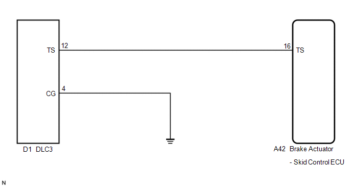
PROCEDURE
|
1. |
CHECK HARNESS AND CONNECTOR (SKID CONTROL ECU - TS of DLC3) |
|
(a) Disconnect the skid control ECU connector. |
|
(b) Measure the resistance according to the value(s) in the table below.
Standard Resistance:
|
Tester Connection |
Condition |
Specified Condition |
|---|---|---|
|
A42-16 (TS) - D1-12 (TS) |
Always |
Below 1 Ω |
|
D1-12 (TS) - Body ground |
Always |
10 kΩ or higher |
|
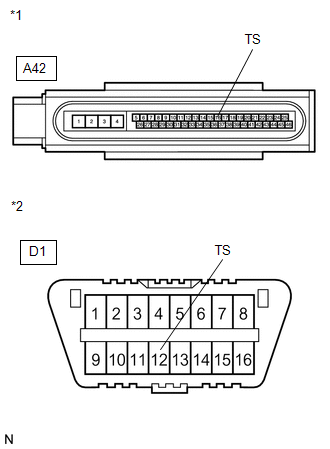
*1 |
Front view of wire harness connector (to Brake Actuator (Skid Control ECU)) |
|
*2 |
Front view of DLC3 |
| NG | .gif) |
REPAIR OR REPLACE HARNESS OR CONNECTOR |
|
.gif)
|
2. |
CHECK HARNESS AND CONNECTOR (CG of DLC3 - BODY GROUND) |
|
(a) Measure the resistance according to the value(s) in the table below. Standard Resistance:
HINT: If troubleshooting has been carried out according to Problem Symptoms
Table, refer back to the table and proceed to the next step before replacing
the part (See page |
|
.gif) ).
)..png)
| OK | |
REPLACE BRAKE ACTUATOR ASSEMBLY |
| NG | |
REPAIR OR REPLACE HARNESS OR CONNECTOR |
 TC and CG Terminal Circuit
DESCRIPTION
Connecting terminals TC and CG of the DLC3 causes the ECU to display the DTC
by blinking the ABS warning and slip indicator lights.
WIRING DIAGRAM
CAUTION / NOTICE / HINT
HINT:
Wh ...
 Vsc Off Switch
Components
COMPONENTS
ILLUSTRATION
Removal
REMOVAL
PROCEDURE
1. DISCONNECT CABLE FROM NEGATIVE BATTERY TERMINAL
NOTICE:
When disconnecting the cable, some systems need to be initialized ...
Other materials about Toyota Venza:
System Diagram
SYSTEM DIAGRAM
Communication Table
Transmitting ECU
Receiving ECU
Signal
Communication Method
Air Conditioning Control Assembly
Air Conditioning Amplifier Assembly
Rear windo ...
Removal
REMOVAL
PROCEDURE
1. REMOVE REAR DOOR SCUFF PLATE RH
HINT:
Use the same procedure for the RH side and LH side (See page
).
2. DISCONNECT REAR DOOR OPENING TRIM WEATHERSTRIP RH
HINT:
Use the same procedure for the RH side and LH side (See page
).
3. ...
Replacement
REPLACEMENT
PROCEDURE
1. REPLACE RING PIN
NOTICE:
It is not necessary to remove the ring pin unless it is being replaced.
(a) Remove the 12 ring pins.
(b) Using a plastic-faced hammer, install 12 new ring pins.
Standard Protrusion Height:
...

0.1182