Toyota Venza: Slip Indicator Light Remains ON
DESCRIPTION
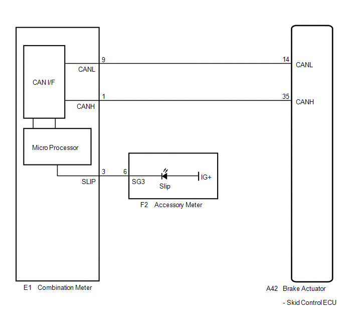
The skid control ECU is connected to the combination meter via CAN communication.
The slip indicator light blinks during VSC and/or TRAC operation.
When the system fails, the slip indicator light comes on to warn the driver (See
page .gif) ).
).
WIRING DIAGRAM
PROCEDURE
|
1. |
CHECK CAN COMMUNICATION SYSTEM |
(a) Check if a CAN communication system DTC is output (See page
).
|
Result |
Proceed to |
|---|---|
|
DTC is not output |
A |
|
DTC is output |
B |
| B | .gif) |
INSPECT CAN COMMUNICATION SYSTEM |
|
.gif)
|
2. |
CHECK IF SKID CONTROL ECU CONNECTOR IS SECURELY CONNECTED |
(a) Check if the skid control ECU connector is securely connected.
OK:
The connector is securely connected.
| NG | |
CONNECT CONNECTOR TO ECU CORRECTLY |
|
|
3. |
CHECK BATTERY |
(a) Check the battery voltage.
Standard voltage:
11 to 14 V
|
Result |
Proceed to |
|---|---|
|
OK |
A |
|
NG (for 2GR-FE) |
B |
|
NG (for 1AR-FE) |
C |
| B | |
CHECK OR REPLACE CHARGING SYSTEM OR BATTERY (for 2GR-FE) |
| C | |
CHECK OR REPLACE CHARGING SYSTEM OR BATTERY (for 1AR-FE) |
|
|
4. |
INSPECT COMBINATION METER ASSEMBLY |
(a) Turn the ignition switch to ON and check the slip indicator light will come on for approximately 3 seconds (initial check).
(b) Perform the Active Test of the combination meter (meter CPU) using the Techstream
(See page ).
(c) Check the accessory meter.
|
Result |
Proceed to |
|---|---|
|
OK |
A |
|
NG (Initial check is normal, and the slip indicator light does not turn on or off in accordance with the Techstream operation) |
B |
|
NG (Initial check is abnormal) |
C |
HINT:
If troubleshooting has been carried out according to Problem Symptoms Table,
refer back to the table and proceed to the next step before replacing the part (See
page ).
| A | |
REPLACE BRAKE ACTUATOR ASSEMBLY |
| B | |
REPLACE COMBINATION METER ASSEMBLY |
| C | |
REPLACE ACCESSORY METER ASSEMBLY |
 Slip Indicator Light does not Come ON
DESCRIPTION
The skid control ECU is connected to the combination meter via CAN communication.
WIRING DIAGRAM
Refer to Slip Indicator Light Remains ON (See page
).
PROCEDURE
1.
...
 TC and CG Terminal Circuit
DESCRIPTION
Connecting terminals TC and CG of the DLC3 causes the ECU to display the DTC
by blinking the ABS warning and slip indicator lights.
WIRING DIAGRAM
CAUTION / NOTICE / HINT
HINT:
Wh ...
Other materials about Toyota Venza:
System Description
SYSTEM DESCRIPTION
1. TOUCH SWITCH OUTLINE
(a) Touch switches are touch-sensitive (interactive) switches operated by touching
the screen. When a switch is pressed, the outer film bends in to contact the inner
glass at the pressed position. By doing this, ...
Installation
INSTALLATION
CAUTION / NOTICE / HINT
HINT:
Use the same procedure for the LH side and RH side.
The following procedure listed is for the LH side.
PROCEDURE
1. INSTALL FRONT LOWER BALL JOINT
(a) Install the front lower ball jo ...
Follow the correction procedures. (smart key system)
After taking the specified steps to correct the suspected problem, check that
the warning light turns off.
- If the malfunction indicator lamp comes on while driving
First check the following:
• Is the fuel empty?
If it is, fill the fuel tan ...

0.1168