Toyota Venza: System Diagram
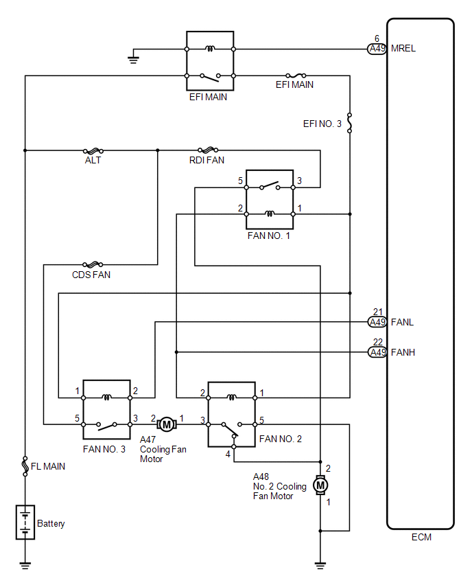
SYSTEM DIAGRAM
 Parts Location
PARTS LOCATION
ILLUSTRATION
...
 Problem Symptoms Table
PROBLEM SYMPTOMS TABLE
Use the table below to help determine the cause of problem symptoms. If multiple
suspected areas are listed, the potential causes of the symptoms are listed in order
of pro ...
Other materials about Toyota Venza:
System Description
SYSTEM DESCRIPTION
1. BACK DOOR CLOSER SYSTEM DESCRIPTION
(a) Operating any power back door switch when the back door is fully closed inputs
a request signal to the power back door ECU*1 or back door closer ECU*2. The power
back door ECU*1 or back door c ...
Room Light
Components
COMPONENTS
ILLUSTRATION
Removal
REMOVAL
PROCEDURE
1. REMOVE SPOT LIGHT ASSEMBLY
(a) Using a screwdriver with its tip wrapped with protective tape, disengage
the 8 claws to remove the 2 spot light lenses.
Text in Illust ...
Front Occupant Classification Sensor RH Circuit Malfunction (B1781)
DESCRIPTION
The front occupant classification sensor RH circuit consists of the occupant
classification ECU and front occupant classification sensor RH.
DTC B1781 is recorded when a malfunction is detected in the front occupant classification
sensor RH c ...

0.1514