Toyota Venza: Parts Location
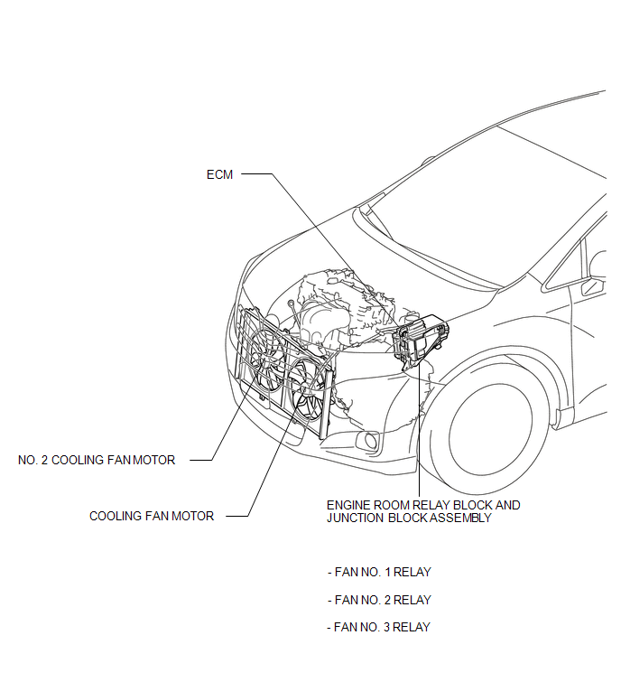
PARTS LOCATION
ILLUSTRATION
 Precaution
PRECAUTION
NOTICE:
When the ignition switch is turned off and the engine temperature is
high, the cooling fans may operate for a maximum of 6 minutes.
After turning the ignition swit ...
 System Diagram
SYSTEM DIAGRAM
...
Other materials about Toyota Venza:
Trouble in Passenger Airbag ON/OFF Indicator
DESCRIPTION
The occupant classification system detects the front passenger seat condition.
It then informs a passenger of the front passenger airbag assembly and front seat
belt pretensioner RH condition (activated/not activated) with the passenger airbag ...
Definition Of Terms
DEFINITION OF TERMS
Term
Definition
Monitor Description
Description of what the ECM monitors and how it detects malfunctions
(monitoring purpose and details).
Related DTCs
Group ...
Seat Heater Switch
Components
COMPONENTS
ILLUSTRATION
Removal
REMOVAL
PROCEDURE
1. REMOVE UPPER CONSOLE PANEL SUB-ASSEMBLY
2. REMOVE SEAT HEATER SWITCH
(a) Disengage the 2 claws and remove the seat heater switch as shown
in the illustration.
...

0.1273