Toyota Venza: System Diagram
SYSTEM DIAGRAM
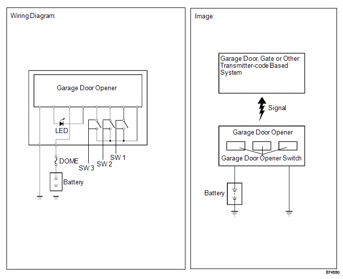
 Parts Location
PARTS LOCATION
ILLUSTRATION
...
 Registration
REGISTRATION
PROCEDURE
1. REGISTER TRANSMITTER CODE
HINT:
The vehicles garage door opener system records transmitter codes for
systems such as garage doors, gates, door locks, home lig ...
Other materials about Toyota Venza:
Installation
INSTALLATION
PROCEDURE
1. TEMPORARILY TIGHTEN FRONT DISC BRAKE BLEEDER PLUG
(a) Temporarily tighten the front disc brake bleeder plug.
HINT:
Fully tighten the front disc brake bleeder plug after bleeding any air left in
the system.
(b) Install the fron ...
AV Signal Stoppage (Low Battery Voltage) (B158F)
DESCRIPTION
This DTC is stored when a video or audio signal is interrupted due to battery
voltage input to the radio and display receiver assembly dropping temporarily.
DTC No.
DTC Detection Condition
Trouble Area
...
Motor Circuit Malfunction (C1522-C1555)
DESCRIPTION
The power steering ECU supplies current to the power steering motor through the
motor circuit.
DTC No.
DTC Detection Condition
Trouble Area
C1522
Motor current sensor malfunction
...

0.1588