Toyota Venza: Installation
INSTALLATION
PROCEDURE
1. TEMPORARILY TIGHTEN FRONT DISC BRAKE BLEEDER PLUG
(a) Temporarily tighten the front disc brake bleeder plug.
HINT:
Fully tighten the front disc brake bleeder plug after bleeding any air left in the system.
(b) Install the front disc brake bleeder plug cap.
2. INSTALL FRONT DISC
|
(a) Align the matchmarks of the disc and axle hub, and install the disc. Text in Illustration
NOTICE: When installing a new disc, select the installation position where the front disc has minimal runout. |
|
.png)
3. INSTALL FRONT DISC BRAKE CYLINDER MOUNTING
|
(a) Install the front disc brake cylinder mounting to the steering knuckle with the 2 bolts. Torque: 104 N·m {1060 kgf·cm, 77 ft·lbf} |
|
.png)
4. INSTALL FRONT DISC BRAKE BUSHING DUST BOOT
|
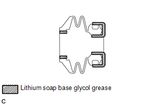
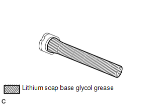
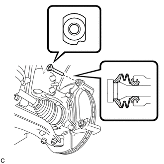
(a) Apply a light layer of lithium soap base glycol grease to the entire circumference of 2 new front disc brake bushing dust boots as shown in the illustration. HINT: Apply at least 0.3 g (0.01 oz.) of lithium soap base glycol grease to each front disc brake bushing dust boot. |
|
|
(b) Install the 2 front disc brake bushing dust boots to the front disc brake cylinder mounting as shown in the illustration. |
|
5. INSTALL FRONT DISC BRAKE CYLINDER SLIDE BUSHING
|
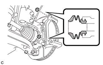
(a) Apply a light layer of lithium soap base glycol grease to the contact surface of a new front disc brake cylinder slide bushing and the No. 2 front disc brake cylinder slide pin. |
|
(b) Install the front disc brake cylinder slide bushing to the No. 2 front disc brake cylinder slide pin.
6. INSTALL NO. 2 FRONT DISC BRAKE CYLINDER SLIDE PIN
|
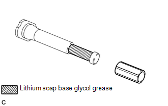
(a) Apply a light layer of lithium soap base glycol grease to the sliding part and the sealing surface of the No. 2 front disc brake cylinder slide pin as shown in the illustration. |
|
|
(b) Install the No. 2 front disc brake cylinder slide pin to the front disc brake cylinder mounting. |
|
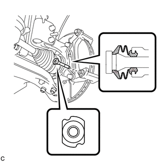
(c) Push the No. 2 front disc brake cylinder slide pin into the front disc brake bushing dust boot to align them.
7. INSTALL FRONT DISC BRAKE CYLINDER SLIDE PIN
|
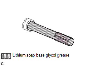
(a) Apply a light layer of lithium soap base glycol grease to the sliding part and the sealing surface of the front disc brake cylinder slide pin as shown in the illustration. |
|
|
(b) Install the front disc brake cylinder slide pin to the front disc brake cylinder mounting. |
|
(c) Push the front disc brake cylinder slide pin into the front disc brake bushing dust boot to align them.
8. INSTALL FRONT DISC BRAKE PAD SUPPORT PLATE
|
(a) Install 2 new front disc brake pad support plates to the front disc brake cylinder mounting. NOTICE: Be sure to install the plate in the correct position and direction. |
|
.png)
9. INSTALL FRONT ANTI-SQUEAL SHIM
|
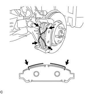
(a) Apply disc brake grease between the front anti-squeal shim and front disc brake pad as shown in the illustration. HINT: Apply 1.0 g (0.03 oz.) of disc brake grease to each pad. |
|
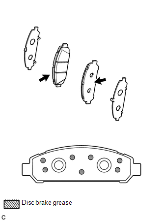
(b) Install the 2 front anti-squeal shims to the front disc brake pads.
NOTICE:
- When replacing worn pads, the front anti-squeal shims must be replaced together with the pads.
- Install the front anti-shims in the correct position and direction.
- Apply disc brake grease to the area that contacts the front anti-squeal shims.
- Disc brake grease can seep out slightly from the area where the front anti-squeal shim is installed.
- Make sure that disc brake grease is not applied onto the lining surface.
10. INSTALL FRONT DISC BRAKE PAD
|
(a) Install the 2 front disc brake pads to the front disc brake cylinder mounting as shown in the illustration. Text in Illustration
NOTICE:
|
|
|
(b) Install the 2 anti-squeal springs to the front disc brake pads. NOTICE:
|
|
11. INSTALL FRONT DISC BRAKE CYLINDER ASSEMBLY
|
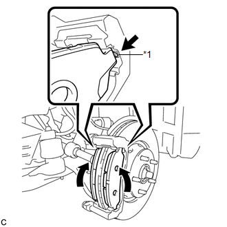
(a) Install the front disc brake cylinder assembly to the front disc brake cylinder mounting with the 2 bolts. Torque: 32 N·m {326 kgf·cm, 24 ft·lbf} NOTICE: Be sure that the anti-squeal springs are installed to the front disc brake pads. |
|
.png)
12. CONNECT FRONT FLEXIBLE HOSE
|
(a) Connect the front flexible hose to the front disc brake cylinder assembly with a new union bolt and a new gasket. Torque: 29 N·m {300 kgf·cm, 22 ft·lbf} HINT: Install the front flexible hose lock securely into the lock hole in the front disc brake cylinder assembly. |
|
.png)
13. FILL RESERVOIR WITH BRAKE FLUID
.gif)
14. BLEED BRAKE LINE
15. INSPECT FOR BRAKE FLUID LEAK
16. INSPECT FLUID LEVEL IN RESERVOIR
17. INSTALL FRONT WHEEL
Torque:
103 N·m {1050 kgf·cm, 76 ft·lbf}
 Inspection
INSPECTION
PROCEDURE
1. INSPECT PAD LINING THICKNESS
(a) Using a ruler, measure the pad lining thickness.
Text in Illustration
*1
Ruler
...
 Front Brake Flexible Hose
Components
COMPONENTS
ILLUSTRATION
Installation
INSTALLATION
CAUTION / NOTICE / HINT
NOTICE:
Because the left and right hoses are not interchangeable, verify the
part number w ...
Other materials about Toyota Venza:
Diagnostic Trouble Code Chart
DIAGNOSTIC TROUBLE CODE CHART
HINT:
If a trouble code is stored during the DTC check, inspect the trouble areas listed
for that code. For details of the code, refer to "See page" below.
1. TRANSPONDER KEY ECU DIAGNOSTIC TROUBLE CODE CHART
Trans ...
Installation
INSTALLATION
CAUTION / NOTICE / HINT
HINT:
Use the same procedure for the RH side and LH side.
The procedure listed below is for the LH side.
PROCEDURE
1. INSTALL POWER WINDOW REGULATOR SWITCH ASSEMBLY
(a) Engage the 2 claws ...
Satellite Radio Broadcast cannot be Received
CAUTION / NOTICE / HINT
NOTICE:
Some satellite radio broadcasts require payment. A contract must be made between
a satellite radio company and the user. If the contract expires, it will not be
possible to listen to the broadcast.
PROCEDURE
1 ...

0.1568