Toyota Venza: Parts Location
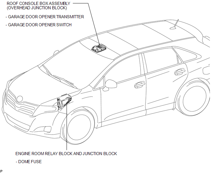
PARTS LOCATION
ILLUSTRATION

 System Diagram
SYSTEM DIAGRAM
...
Other materials about Toyota Venza:
Personal/interior lights
► Front
On/off
The illuminated entry system is activated even if the light is turned off when
the personal/interior light main switch is in door position.
► Rear
On/off
The illuminated entry system is activated even if the light is turne ...
Amplifier Antenna
Components
COMPONENTS
ILLUSTRATION
Removal
REMOVAL
PROCEDURE
1. REMOVE BACK DOOR PANEL TRIM ASSEMBLY
2. REMOVE AMPLIFIER ANTENNA ASSEMBLY
(a) Disconnect the 2 connectors.
(b) Remove th ...
Installation
INSTALLATION
PROCEDURE
1. INSTALL BRAKE ACTUATOR ASSEMBLY
(a) Install the brake actuator assembly to the brake actuator bracket
assembly with the 2 nuts.
Torque:
8.0 N·m {82 kgf·cm, 71 in·lbf}
NOTICE:
Do not remov ...

0.1745