Toyota Venza: Motor Circuit Malfunction (C1522-C1555)
DESCRIPTION
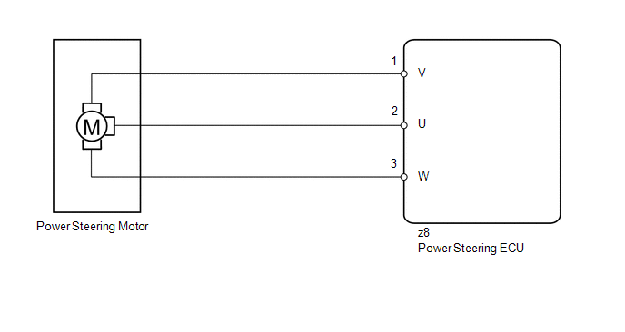
The power steering ECU supplies current to the power steering motor through the motor circuit.
|
DTC No. |
DTC Detection Condition |
Trouble Area |
|---|---|---|
|
C1522 |
Motor current sensor malfunction |
|
|
C1523 |
Excessively large current deviation |
|
|
C1524 |
Short (or open) in motor circuit or abnormal voltage or current in motor circuit |
|
|
C1555 |
Motor relay failure |
WIRING DIAGRAM
CAUTION / NOTICE / HINT
NOTICE:
If the power steering ECU and steering column assembly have been replaced, perform
the rotation angle sensor initialization and torque sensor zero point calibration
(See page .gif) ).
).
PROCEDURE
|
1. |
READ VALUE USING TECHSTREAM (MOTOR VOLTAGE) |
(a) Turn the ignition switch off.
(b) Connect the Techstream to the DLC3.
(c) Turn the ignition switch to ON.
(d) Turn the Techstream on.
(e) Enter the following menus: Chassis / EMPS / Data List.
(f) Select the items "Motor Terminal Volt(U)", "Motor Terminal Volt(V)" and "Motor Terminal Volt(W)" in the Data List and read the value displayed on the Techstream.
EMPS|
Tester Display |
Measurement Item/Range |
Normal Condition |
Diagnostic Note |
|---|---|---|---|
|
Motor Terminal Volt(U) |
Motor terminal voltage (U phase)/ Min.: 0 V Max.: 46.667 V |
During steering operation, value changes within 4 to 46 V range |
The engine is running and steering wheel is being turned. |
|
Motor Terminal Volt(V) |
Motor terminal voltage (V phase)/ Min.: 0 V Max.: 46.667 V |
During steering operation, value changes within 4 to 46 V range |
The engine is running and steering wheel is being turned. |
|
Motor Terminal Volt(W) |
Motor terminal voltage (W phase)/ Min.: 0 V Max.: 46.667 V |
During steering operation, value changes within 4 to 46 V range |
The engine is running and steering wheel is being turned. |
|
Result |
Proceed to |
|---|---|
|
During steering operation, value changes within 4 to 46 V range |
A |
|
During steering operation, voltage is not generated |
B |
| A | .gif) |
REPLACE POWER STEERING ECU |
| B | |
REPLACE STEERING COLUMN ASSEMBLY |
 Vehicle Speed Signal Malfunction (C1541)
DESCRIPTION
The power steering ECU receives vehicle speed signals from the brake actuator
assembly (skid control ECU) via CAN communication. The ECU provides appropriate
assisting force in accord ...
 Torque Sensor Zero Point Adjustment Incomplete (C1516,C1526)
DESCRIPTION
These DTCs do not indicate a malfunction. The power steering ECU stores these
DTCs when it determines that the rotation angle sensor value initialization and
torque sensor zero point ...
Other materials about Toyota Venza:
Transponder Key Amplifier
Components
COMPONENTS
ILLUSTRATION
Removal
REMOVAL
PROCEDURE
1. REMOVE FRONT DOOR SCUFF PLATE
2. REMOVE COWL SIDE TRIM SUB-ASSEMBLY
3. REMOVE LOWER NO. 1 INSTRUMENT PANEL FINISH PANEL
4. REMOVE LOWER STEERING COLUMN COVER
5. REMOVE ...
Precaution
PRECAUTION
1. INITIALIZATION
NOTICE:
Perform the Registration (VIN registration) when replacing the ECM (See page
).
HINT:
Reset memory or initialization cannot be completed by only disconnecting and
reconnecting the cable of the negative (-) battery ...
Auxiliary boxes
►Type A (driver’s side instrument panel)
Push down the knob.
►Type B (front console)
Lift the lid.
►Type C (front console)
Lift the lid.
►Type D (front passenger’s side instrument
panel)
- Coin holder (type A) ...

0.1351