Toyota Venza: System Diagram
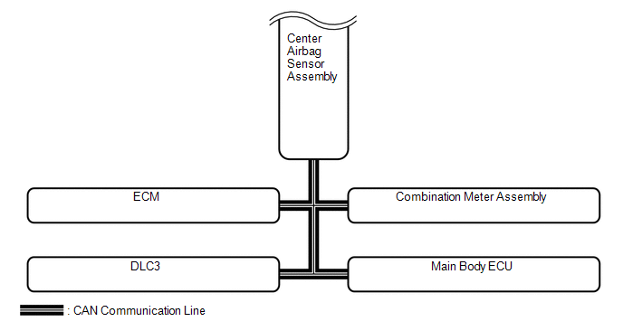
SYSTEM DIAGRAM
|
Transmitting ECU (Transmitter) |
Receiving ECU |
Signal |
Communication Method |
|---|---|---|---|
|
Center Airbag Sensor Assembly |
ECM |
Crash detection signal |
CAN |
|
Combination Meter Assembly |
|
||
|
Main Body ECU |
Driver seat buckle switch signal |
||
|
ECM |
Center Airbag Sensor Assembly |
|
|
|
Combination Meter Assembly |
Vehicle speed signal |
 Parts Location
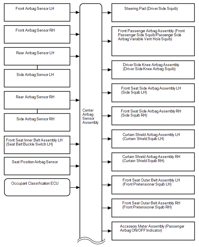
PARTS LOCATION
ILLUSTRATION
ILLUSTRATION
...
 How To Proceed With Troubleshooting
CAUTION / NOTICE / HINT
HINT:
*: Use the Techstream.
PROCEDURE
1.
VEHICLE BROUGHT TO WORKSHOP
NEXT
...
Other materials about Toyota Venza:
Installation
INSTALLATION
PROCEDURE
1. REPAIR INSTRUCTION
2. INSTALL REAR DOOR LOWER OUTSIDE STRIPE
(a) Refer to the illustration to position the rear door lower outside stripe.
Standard Measurement
Dimension
Measurement
A
...
Removal
REMOVAL
PROCEDURE
1. REMOVE REAR DOOR SCUFF PLATE
2. DISCONNECT REAR DOOR OPENING TRIM WEATHERSTRIP
3. REMOVE TONNEAU COVER ASSEMBLY (w/ Tonneau Cover)
4. REMOVE DECK BOARD ASSEMBLY
5. REMOVE NO. 3 DECK BOARD SUB-ASSEMBLY
6. REMOVE DECK S ...
Open in Occupant Classification ECU Battery Positive Line (B1794)
DESCRIPTION
This circuit consists of the occupant classification ECU and power source circuit
(battery, fuse and wire harness).
DTC B1794 is recorded when a malfunction is detected in the occupant classification
ECU or power source circuit.
HINT:
If DT ...

0.1566