Toyota Venza: Parts Location
PARTS LOCATION
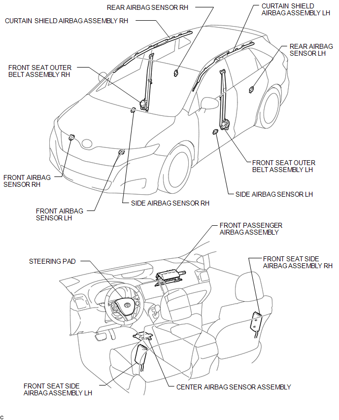
ILLUSTRATION
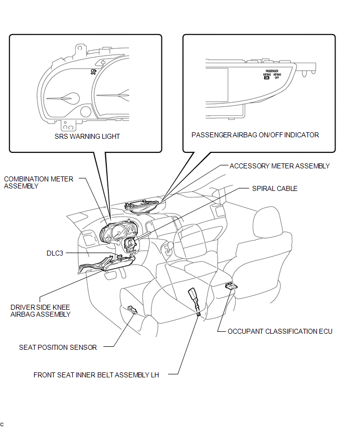
ILLUSTRATION
 Precaution
PRECAUTION
HINT:
In the airbag system, the front airbag sensor, door side airbag sensor
and rear airbag sensor are collectively referred to as the airbag sensors.
The steering pad ...
 System Diagram
SYSTEM DIAGRAM
Transmitting ECU
(Transmitter)
Receiving ECU
Signal
Communication Method
Center Airbag Sensor Assembly
EC ...
Other materials about Toyota Venza:
Removal
REMOVAL
PROCEDURE
1. REMOVE UPPER CONSOLE PANEL SUB-ASSEMBLY (w/o Seat Heater System)
2. REMOVE UPPER CONSOLE PANEL SUB-ASSEMBLY (w/ Seat Heater System)
3. REMOVE NO. 2 CONSOLE BOX CARPET
(a) Remove the No. 2 console box carpet.
...
Problem Symptoms Table
PROBLEM SYMPTOMS TABLE
HINT:
Use the table below to help determine the cause of problem symptoms.
If multiple suspected areas are listed, the potential causes of the symptoms
are listed in order of probability in the "Suspected Area" ...
Removal
REMOVAL
PROCEDURE
1. REMOVE YAW RATE AND ACCELERATION SENSOR
HINT:
Refer to the instructions for Removal of the yaw rate and acceleration sensor
(See page ).
2. REMOVE REAR NO. 2 AIR DUCT
3. REMOVE REAR NO. 1 AIR DUCT
4. REMOVE FRONT NO. 2 FLOO ...

0.1236