Toyota Venza: Inspection
INSPECTION
PROCEDURE
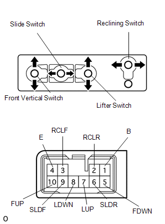
1. INSPECT FRONT POWER SEAT SWITCH LH (w/o Seat Position Memory System)
|
(a) Measure the resistance between the terminals when each switch is operated. Standard Resistance: Slide Switch
If the result is not as specified, replace the switch. |
|
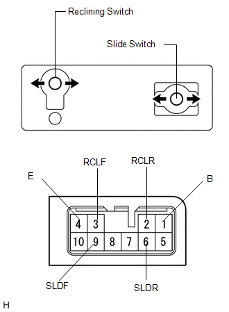
2. INSPECT FRONT POWER SEAT SWITCH RH (w/o Seat Position Memory System)
|
(a) Measure the resistance between the terminals when each switch is operated. Standard Resistance: Slide Switch
If the result is not as specified, replace the switch. |
|
 Removal
REMOVAL
PROCEDURE
1. REMOVE FRONT SEAT HEADREST ASSEMBLY
2. REMOVE FRONT SEAT REAR OUTER TRACK COVER
3. REMOVE FRONT SEAT REAR INNER TRACK COVER
4. REMOVE FRONT SEAT ASSEMBLY
5. REMOVE ...
 Installation
INSTALLATION
PROCEDURE
1. INSTALL POWER SEAT SWITCH
(a) Install the power seat switch with the 3 screws.
(b) Connect the connector.
2. IN ...
Other materials about Toyota Venza:
Chassis
General Maintenance
GENERAL MAINTENANCE
PROCEDURE
1. INSPECT STEERING LINKAGE AND GEAR HOUSING
(a) Check the steering wheel free play (See page
).
(b) Check the steering linkage for looseness or damage.
(1) Check that the tie rod ends do not have any ...
USB Media Malfunction (B1585)
DESCRIPTION
This DTC is stored when a malfunction occurs in a connected device.
DTC No.
DTC Detection Condition
Trouble Area
B1585
When any of the following conditions is met:
A non m ...
Customizable features
1. Vehicles with TFT type multi-information display: Some function settings can
be changed by operating the multi-information display.
2. Settings that can be changed by your Toyota dealer
Definition of symbols: O = Available, -- = Not available
...

0.129