Toyota Venza: System Diagram
SYSTEM DIAGRAM
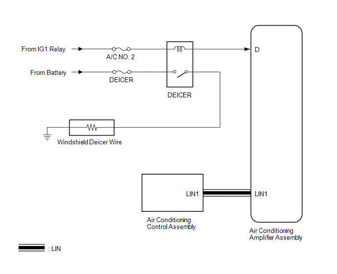 Communication Table
|
Transmitting ECU |
Receiving ECU |
Signal |
Communication Method |
|---|---|---|---|
|
Air Conditioning Control Assembly |
Air Conditioning Amplifier Assembly |
Rear window defogger switch signal |
LIN |
 Parts Location
PARTS LOCATION
ILLUSTRATION
ILLUSTRATION
...
 How To Proceed With Troubleshooting
CAUTION / NOTICE / HINT
HINT:
Use the following procedure to troubleshoot the windshield deicer system.
PROCEDURE
1.
VEHICLE BROUGHT TO WORKSHOP
...
Other materials about Toyota Venza:
Position Initialization Incomplete (B2343)
DESCRIPTION
This DTC is output when the sliding roof ECU (sliding roof drive gear sub-assembly)
has not been initialized.
DTC Code
DTC Detection Condition
Trouble Area
B2343
Sliding roof ECU (sli ...
Installation
INSTALLATION
PROCEDURE
1. INSTALL NO. 3 ANTENNA CORD SUB-ASSEMBLY
(a) Pass the washer hose through the No. 3 antenna cord sub-assembly.
(b) Pass the No. 3 antenna cord sub-assembly with washer hose through
the vehicle body as shown in the il ...
Removal
REMOVAL
CAUTION / NOTICE / HINT
HINT:
Perform "Inspection After Repair" after replacing the fuel injector assembly
(See page ).
PROCEDURE
1. DISCHARGE FUEL SYSTEM PRESSURE
(a) Discharge fuel system pressure (See page
).
2. DISCONNECT CABL ...

0.114