Toyota Venza: Parts Location
PARTS LOCATION
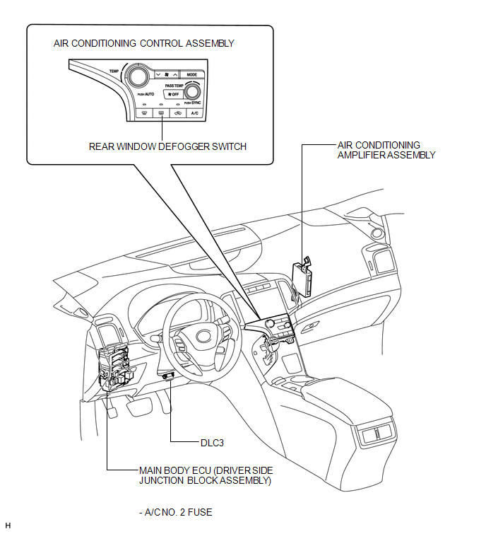
ILLUSTRATION
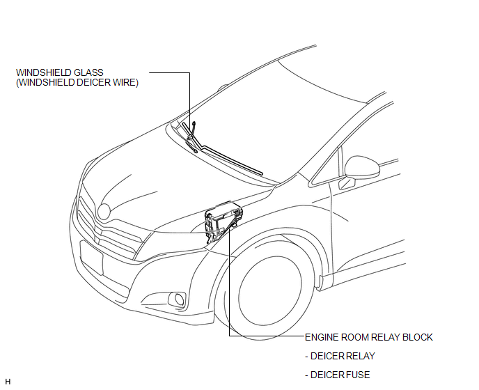
ILLUSTRATION
 Precaution
PRECAUTION
NOTICE:
When disconnecting the cable from the negative (-) battery terminal, initialize
the following systems after the cable is reconnected.
System Name
See Proc ...
 System Diagram
SYSTEM DIAGRAM
Communication Table
Transmitting ECU
Receiving ECU
Signal
Communication Method
Air Conditioning Control Assembly
...
Other materials about Toyota Venza:
Diagnostic Trouble Code Chart
DIAGNOSTIC TROUBLE CODE CHART
HINT:
If a trouble code is stored during the DTC check, inspect the trouble areas listed
for that code. For details of the code, refer to the "See page" below.
Certification ECU (Smart Key ECU Assembly)
...
XM Tuner Antenna Disconnected (B15FE,B15FF)
DESCRIPTION
These DTCs are stored when a malfunction occurs in the roof antenna assembly
which is connected to the stereo component tuner assembly.
DTC No.
DTC Detection Condition
Trouble Area
B15FE
...
No Sound can be Heard from Speakers
PROCEDURE
1.
CHECK AUDIO SETTINGS
(a) In sound setting mode, set volume, fader and balance to the initial values
and check that the sound is normal.
OK:
Audio system returns to normal.
HINT:
Sound quality adjustment mea ...

0.1362